
Introduction to H1E
The H1E eScore target is a next generation electronic target based on acoustic sensors. It works with subsonic and supersonic ammunition and is designed to be used at 100-200 meter ranges, though not restricted to these distances..
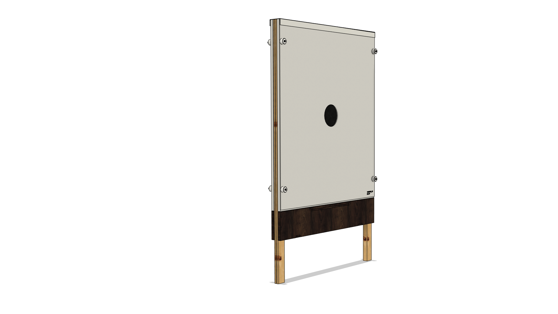
Features of the H1E target
- 4 acoustic sensors, one in each corner of the target
- Horizontal and vertical rubber bands available
- Wide range of target faces are available
- Guide pin design allows swift change of target face, without need for additional zero point adjustment.
- Can be used with both subsonic projectiles like .22LR and supersonic projectiles like .223, .308, 30-06, 6.5
Technical specifications and dimensions
A |
1160 mm |
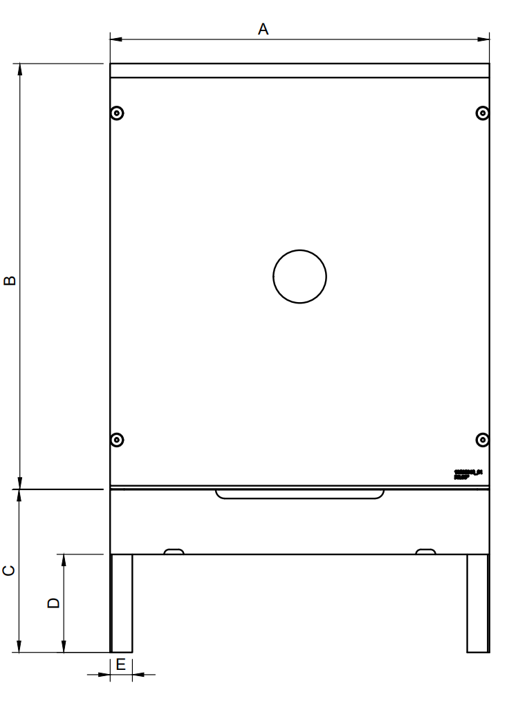 |
B |
1300 mm |
|
C |
500 mm |
|
D |
300 mm |
|
E |
68 mm |
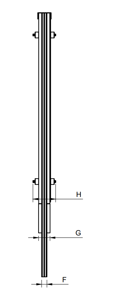 |
F |
36 mm |
|
G |
92 mm |
|
H |
155 mm |
| Temperature range | -30 to +60 °C |
| Weight | ~ 25 kg |
| Power consumption | ~ 4.4W @ 24 VDC |
| Calibers | Subsonic and supersonic projectiles |
Exploaded view and parts list
E-target configurations

| Item | Part name | KTS part no. |
| 1 |
The target → Target H1E - eScore → Target U7E - eScore |
13020001 13020315 |
| 3 | Main target rubber skin (2pcs pr target) | 97020075 |
| 6 |
Guide pins (4pcs pr target) → threaded centre → non threaded centre → headed, non threaded center |
97020728 97020850 97020845 |
| 7 | Front temperature shield |
Several available See table below |
| 8 | Foam sheet insert |
Several available See table below |
| 9 | Rear temperature shield | 13020109 |
| 10 | Target face |
Several available See table below |
| 11 | Fixation nut (8pcs pr target) | 97020729 |
| 14 | Male I/O cable |
Amphenol: 13020209 M23: 13020190 |
| 15 | Female I/O cable |
Amphenol: 13020210 M23: 13020191 |
| 16 | Horizontal rubber band | 97020380 (35cm wide) |
| Vertical rubber band | 97020192 (46cm wide) | |
| 18 | Top cover | 97020527 - 116cm |
Front temperature shields available
Abbr. part name |
KTS part no. |
Target setup no. |
Illustration |
P30E |
13020108 |
#1 |
 |
P40E |
13020126 |
#2 |
 |
P60E |
13020124 |
#3 |
 |
Foam sheet inserts available
| Abbr. part name | KTS part no. | Fits target setup no. |
| FS 30x30/35x35 | 13020155 | #1 |
| FS 40x40/50x50 | 13020158 | #2 |
| FS 60x60/70x70 | 13020154 | #3 |
| FS 60x60/120x80 | 13020213 | #3 |
Target faces available
| Abbr. part name | KTS part no. | Fits target setup no. | Fits target scoring definition no. |
| R13'' | 13020311 | 1, 2, 3 | 369 |
| R6.35'' | 13020310 | 1, 2, 3 | 372 |
| 1/10-fig | 13020022 | 1, 2, 3 | 155 |
| C20-fig | 13020036 | 1, 2, 3 | 278 |
| C25-fig | 13020037 | 1, 2, 3 | 350 |
| 1/8-fig | 13020041 | 2, 3 | 348 |
| (10/30)-fig | 13020046 | 1, 2, 3 | 353 |
| (30/10)-fig | 13020047 | 1, 2, 3 | 277 |
| ⅓-fig | 13020153 | 3 | 38 |
| R20 | 13020323 | 1, 2, 3 | 7, 77, 169, 269 |
| R60 | 13020415 | 3 | 3, 6, 21, 196, 217, 288, 295 |
| ¼-fig | 13020275 | 2, 3 | 39 |
| 1/4V-fig | 13020169 | 2, 3 | 429 |
| C30-fig | 13020038 | 2, 3 | 40 |
| 1/6-fig | 13020040 | 3 | 279 |
| S25H-fig | 13020043 | 3 w/13020213 | 351 |
| (13/40)-fig | 13020044 | 2, 3 | 276 |
| (40/13)-fig | 13020045 | 2, 3 | 352 |
| S25V-fig | 13020152 | 3 w/13020213 | 356 |
| Småen-fig | 13020168 | 1, 2, 3 | 113 |
| IPSC V2 | 13020299 | (*Note 2) | 440 |
| R24 | 13020144 | 1, 2, 3 | 1, 92 |
| R40 | 13020312 | 2, 3 | 2, 4, 170, 399 |
| B45-fig | 13020371 | 2, 3 | 354 |
| C40-fig | 13020413 | 2, 3 | 357 |
| Tønne-fig | 13020165 | 1, 2, 3 | 164 |
| Blank | 13020292 | 1, 2, 3 | All (*Note1) |
| C15-fig | 13020023 | 1, 2, 3 | 156 |
| P-Fig | 13020369 | 1, 2, 3 | 453 |
| D-Fig | 13020368 | 1, 2, 3 | 452 |
| Fiskebeck | 13020390 | 3 w/13020213 | 447 |
| Mini P-fig | 13020365 | 1, 2, 3 | 450 |
| Mini 1/9-fig | 13020385 | 1, 2, 3 | 448 |
| Dråpe-fig | 13020386 | 1, 2, 3 | 449 |
| 1/9-fig | 13020372 | 1, 2, 3 | 451 |
| Reindeer | 13020346 | 1, 2, 3 | 64 |
| Hor prism-fig | 13020028 | 1, 2, 3 | 161 |
| Minismåen-fig | 13020027 | 1, 2, 3 | 160 |
| Mini ¼-fig | 13020026 | 1, 2, 3 | 159 |
| Hjul (finfelt)-fig | 13020024 | 1, 2, 3 | 157 |
| Mini ⅓-fig | 13020025 | 1, 2, 3 | 158 |
| Circle-fig | 13020029 | 1, 2 , 3 | 162 |
| R18 | 13020150 | 1, 2, 3 | |
| C50-fig | 13020151 | (2), 3 | 358 |
| IPSC Mini V2 | 13020300 | 2, 3 | 439 |
| Hor stripe-fig | 13020030 | 1, 2, 3 | 163 |
Note1: This target face is all-white and may be fitted with any target figures by customer.
Note2: This target face is black. White spot is intended, by adding white contrast sheet (KTS part no: 140205409).
Target Rubbers
|
The target is fitted with a target rubber skin (both at the front of the target frame and at the back) and a rubber band to obtain a soundproof measuring chamber in between.
The target rubber skins are fitted with a Ø35/Ø25cm hole in the centre section, to reduce wear affecting scoring accuracy. |

|
|
To keep a sound proof measuring chamber, and ease maintenance, the target is fitted with a vertical rubber band, and sometimes a horizontal rubber band. The vertical rubber band should always touch and cover the cut-out holes in the target rubber skins.
See later chapter about the use of rubber bands, target maintenance and rotation of target rubber bands. |

|
Dismantling
See exploded view and parts list in accordion above.
Target assembly must be partly disassebled when doing maintenance. Top cover is attached to target with Velcro, and is simply pulled up to be picked off. Other parts can be picked off after unscrewing guide pin nuts.
H target video disassembly
Your browser does not support HTML5 video....
H1E target maintenance
Replacement or rotation of rubber band. Replacing foam sheet.
The rubbers at target is worn by penetrating projectiles. This will eventually cause noise to enter the soundproof measuring chamber inside the target.

Such wear normally occurs in the center of the target. To ease maintenance and lower maintenance cost the target is fitted with one or two rubber bands and a foam sheet insert that is covering the centre of the target.
The vertical rubber band must cover the hole, pre-cut or later cut out, of the target rubber skin. This rubber band is intended to be rotated up at the front, and down at the back of the target - to eliminate the wear at centre.
The horizontal rubber band shall not be used when the target is used for cal .22LR. This rubber band is only beneficial when target is used for big bore calibres, thus enabelig less rotation each time (and less frequent).
When rubber bands are rotated, the foam sheet should also be replaced.
How often this maintenance is needed depends on calibres in use, bullet shapes, shooting distance and shooter skills (grouping). As a rule of thumb, for this target model, we recommend following intervals based on following shooting distances:
| Shooting distance | Caliber notes | Rotational frequency |
| 100 m | Using small bore calibers (.22LR, sub-sonic projectiles) together with big bore. Using only vertical rubber band. | After 500 rounds |
| 100 m | Using only big bore calibers (supersonic projectiles), and horizontal+vertical rubber bands. | After 1000 rounds |
| 200 m | Only big bore. Horizontal+vertical rubber bands. | After 1500 rounds |

Note that the table above assumes normal full jacketed bullets (except 22LR) and relatively good groupings. If groupings are larger the intervals can be even longer. The use of hunting ammunition may call for more frequent maintenance.
The splice of the rubber band should always be kept at the back of the target. Avoid having the splice at center of target, until the last leg of the rubber band is used.
The rubber band need to be rotated approximately ½ of the diameter of the cut-out section of the front target rubberskin (leaving fresh rubber at center), if the rubber band isn't worn excessively. For a new target, this would be approcimately 15-20cm (6-8'').
When the horizontal rubber band eventually is rotated ½ roud, it needs to be replaced with a new one. In this event, the upper guide pins need to be removed before putting the new rubber band at target. Soap in spray bottle might be helpful when replacing rubber band, to reduce friction.
VIDEO
Ensure that the rubber band is put tightly against the target rubber skin.
Please note that the scoring system has shot counters that may be reset when doing maintenance - to keep track of shot numbers.
Inspecting and replacing the temperature shields
The temperature shields task is to obtain an even temperature inside the target, even if the target is exposed to sunlight. The temperature shields are also worn by the projectiles. Typically the rear temperature shield is worn in the centre section.
| Rear temperature shield will start swelling after a few hundread rounds. |  |
| To awoid collapse of measuring chamber, the rear temperature shield is fitted with a a rip-off section. |  |
| Rip off when rear temperature shield start swelling, and put the temperature shield back at target with the rip-off section facing target rubber skin. |  |
Expect to replace rear temperature shield when the hole has a diameter of 40cm (15'').
The temperature shields are also worn by sunlight and other environmental factors. Expect to replace when the temperature shields doesn't maintain physical integrity.
Repair ricochet damages to target rubber skin
In the event of projectiles passing through the target as they are tilted or otherwise deformed, they may generate large holes in the target rubber skins.
If the large holes occur in the center of the rubber band(s), scoring issues are prevented by rotating.
If the large holes occur at the main target rubber skin, outside the rubber band, the holes need to be patched. This is done by spray glue and a piece of adhesive tape, or fast curing super glue and a piece of rubber.
Inspecting the target rubber skin
The target rubber skin need to be replaced in these events:
| 1. |
Excess wear (large number of shot holes) at target rubber skin will affect scoring accuracy. This is especially important at the edge of the cut-out of the front target rubber skin. This phenomena is particularly bad when the rubber sheet doesn't hold together, and coin sized parts start dangling.
If edge of cut-out is poor, as described above, the size of the cut-out may be increased by use of scissors. However, it is outmost important that the rubber band still is covering the cut-out with good margins (3-4cm). |
| 2. | As the target rubber skin is aging, its tensile strength will degrade. The target measuring chamber (between the target rubber skins) may eventually implode if the target is subjected to wind. Implosions can be temporarily be fixed by detaching, stretching and reattaching the target rubber skin. |
| 3. | As the target rubber skin is aging, it will eventually start to crack. Cracks may become holes and compromise the sound proof measuring chamber. |
Inspecting and cleaning sensos
The lower sensors (behind the service panel) are rarely subjected to dust and particles as they are put far out to the side. Cleaning them with a soft brush is normally not necessary more often than when replacing target rubber skins.
However, periodic inspection may be called for, if the inner edge of the target frame is hit by stray bullets. Splinters and woodchips may then cover the sensors, and should be removed.
Warning!
Do not use excess forse when brushing, thus dislocating the sensors.
Inspecting the target face
Target faces are worn by penetrating projectiles. They should be replaced if they provide a poor target profile for the shooter. Fixation nuts (at front of the target) and top cover must be taken off before replacing target face.
Inspecting the target service panel
The lower part of the target has a service panel that can be opened to access the target electronics and the lower sensors. Opening and closing is done by detaching the white rubber straps at the bottom of the target.
Inspect the physical integrity of the service panel and its hinges/straps, and check that it's possible to close completely. There should be no cracks that sound can “leak” through when the service panel is closed. Always keep the service panel closed and strapped, expect when servicing or inspecting the internals of the target.
The white rubber straps will deteriorate over time, and must be replaced when tensile strenght becomes poor.
Inspecting the sensor cables
Sensor cables are put at the outside of the target frame (left and right side). Inspect the outer 10mm of the target frame to see if any stray projectiles possibly has penetrated or snatched any cables. If so, see next chapter how to repair. Sensor cables are easily picked out of the cable channels at the sides of the target to be inspected or replaced.
If sensor cables are completely cut or short circuited, the scoring system will publish warnings, and damaged target will probably stop scoring. However, a snatched or partially damaged cable may not cause problems before it's exposed to moisture. It is therefore wise to periodically evaluate the sensor cables if stray shots has penetrated close to, or trough, the cable channels.
Target repairs and spare parts
Repairs
Repairing sensors or wiring
Whenever an H-target model is used, one runs the risk of a shooter hitting the up...
Stray shots risk hitting the upper acoustic sensors, upper temperature sensor or their wiring. This section explains how to repair in these cases.
Repairing sensor wiring
To simplify repairs, all upper sensor wirings are run on the outskirt of the target frame. In the case of a bullet or ricochet cutting a sensor cable, the target electronics will detect that something is wrong with the sensor and also provide warnings to the scoring system. Additionally the circuit board inside the target (the target electronics) will display sensor status by use of LEDs. This circuit board is accessible behind the service panel at the bottom of the target.
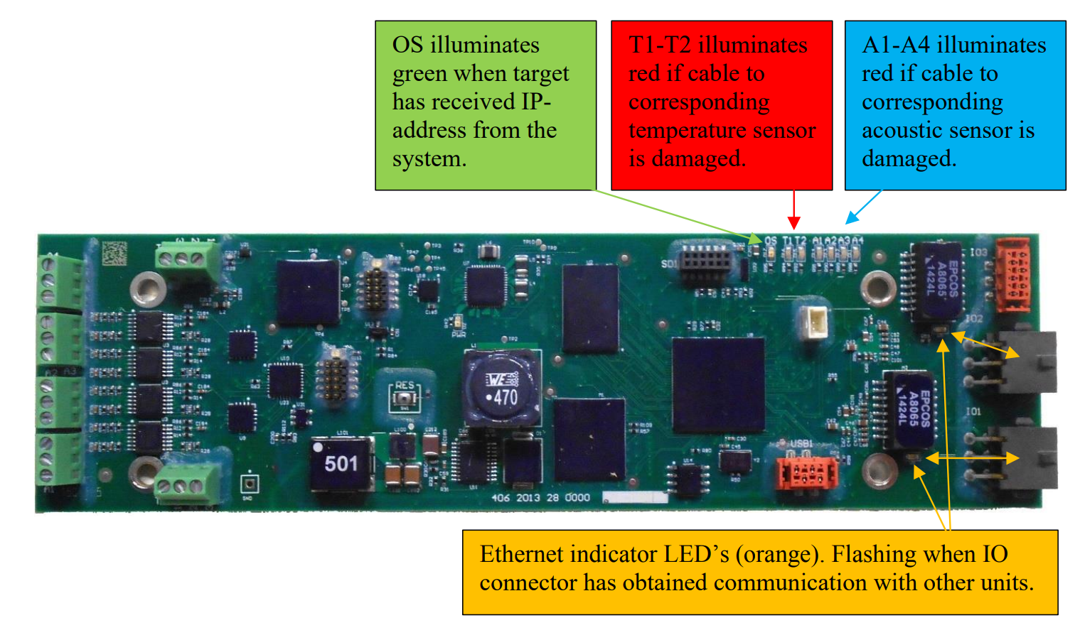
Sensor cables may be temporarily spliced with butt splices. However, as a permanent repair cables should be spliced by soldering and sealed with heat shrink tube - if sensor cable isn't replaced. Please also splice the un-isolated leader in the sensor cables.
Replacing sensors
In some cases it might be easier or necessary to replace the entire sensor with wiring harness.
The sensor wires are attached to their respective numbered terminal blocks according to the tables below:
| Connector No. | Attached sensor |
| A1 | Upper right acoustic sensor |
| A2 | Lower right acoustic sensor |
| A3 | Lower left acoustic sensor |
| A4 | Upper left acoustic sensor |
| T1 | Lower temperature sensor |
| T2 | Upper temperature sensor |
The teminal blocks are found at the left side of the board (green components at the image above). Teminal block A1 is the lower left, followed by A2, A3 and the A4 is the upper left block. Each connection point of each termainal block are individually numbered 1, 2 and 3.
For sensors A1-A4 the sensor cable is connected to the terminal blocks as follows:
| Wire | Connection point |
| Red | 1 |
| Black | 2 |
| Cable screen / Ground | 3 |
For sensor T2 the sensor cable is connected to its teminal block as follows:
| Wire | Connection point |
| White | 1 |
| Black | 2 |
| Cable screen / Ground | 3 |
For sensor T1 the sensor cable is connected to its terminal block as follows:
| Wire | Connection point |
| Red | 1 |
| Green | 2 |
| Yellow | 3 |
Replacing the upper acoustic sensors
If the upper sensors are to be replaced a section (corner) of the target rubber skin must be detached the target frame to access the sensor(s). We recommend accessing from the front of the target. The acoustic sensors are taped to an aluminum bracket that is screwed into the target frame.
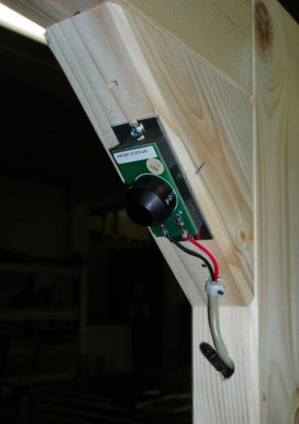 Upper right acoustic sensor mounted on aluminum bracket. The upper right temperature sensor is also visible.
Use the same screws and screw holes when replacing the sensor.
The temperature sensor is supposed to extend only 2-3 cm inside the target frame.
Replacing I/O cables
I/O cables are pre fabricated to specific lengths. The male and the female I/O cables are connected to the target electroniscs IO1 and IO2 box connectors at the right side of the board. Also, cable ground wires are screwed to the metal of which the target electronics is attached.


When ordering I/O cables make sure to choose the connector series fitting rest of the system. See exploaded view parts list at top of this user manual to find part numbers.
I/O cables are attached to target frame with cable clamps and a and some adhesive tape. Install the cables as the original cable harness. Get some cable ties before replacing cables, in addition to canvas tape.
I/O cables are always put in a loop inside target, to obtain maximum strain relief. Prevent loop from touching any nearby sensors by bending the loop in combination with using cable clips. Images below from different target models:
 |
 |
I/O cables should extend approximately 14cm from the underside of the target frame.

Spare parts
H-target common spare parts
| KTS part no | Description | Image |
| 97020851-240cm | Acoustic sensor with mounting plate | |
| 97020522-220cm | Upper temperature sensor cable | |
| 97020842 | Lower temperature sensor | |
| 13020209-85cm | Male I/O cable (Amphenol) | |
| 13020210-85cm | Female I/O cable (Amphenol) | |
| 13020190 | Male I/O cable (M23) | |
| 13020191 | Female I/O cable (M23) | |
| 97020517 | Target electronics mounting bracket | |
| 97020812 | Target electronics cover | |
| 97020728 | Guide pin (threaded centre) | |
| 97020850 | Guide pin (non threaded centre) | |
| 97020845 | Guide pin (headed, non threaded centre) | |
| 97020729 | Guide pin nut | |
| 1502007 | Hinge | |
| 1507012 | Rubber strap | |
| 1507013 | Cannopy button | |
| 97020532 | Assembly plate | |
| 97020722 | Rubber gasket (underneath assembly plate) | |
| 1302004 | Duct tape | |
| 1302007 | Spray glue |
| 13280000-H1E | Target electronics | |
| 97020527-116cm | Target top cover | |
| 97020146 | Aluminum list | |
| 97020582 | Target service panel | |
Protection of the H1E Target
How to protect the H1E Target from bullets and ricochets
Protecting the eScore acoustic target
The eScore targets have the critical electronics located at the bottom of the tar
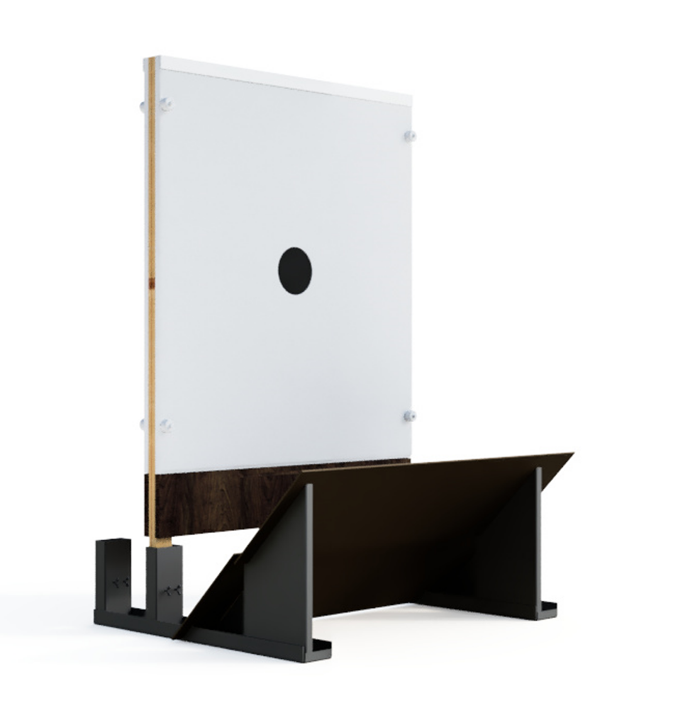
The targets have the most critical, or all, electronic components located at the bottom of the target - behind the service panel. To minimize maintenance cost and maintain the target durability it is recommended to protect this section of the target by use of a knee wall or protective plates. Target stands with protective plates are available on request.
Please refer to this YouTube video for recommendations on how to install the targets.
Protection from ricochets and shrapnel
Some shooting ranges have backstop that create shrapnel when bullets hit bullet catchers. This should be avoided since cables may be cut or short circuited by shrapnel or bullet jackets. To minimize the effects careful placement of the wiring between targets, antennas, batteries etc. must be done. If steel bullet catcher is used, make sure to cover it with rubber material or other absorbent material to minimize ricochets and shrapnel exiting the bullet catcher.