
Introduction to H2B
The H2B eScore target (KTS part no 13020454) is a next generation electronic target based on acoustic sensors. It works with both sub- and supersonic ammunition. It is designed to be used for 50-100 m/yds shooting ranges, particularly suited as a running target. It is often fitted with animal figures.

Features of the H2B target
- 4 acoustic sensors, one in each corner of the target, for optimal scoring accuracy.
- Closed chamber acoustic detection system, unaffected by weather conditions.
- Guide pin design allows swift dismounting and mounting of target face, without need for subsequent zero point alignment.
Technical specifications and dimensions
A |
1500 mm |
 |
B |
900 mm |
|
C |
500 mm |
|
D |
300 mm |
|
E |
70 mm |

|
F |
45 mm |
|
G |
98 mm |
|
H |
145 mm |
| Temperature range | -30 to +60 °C |
| Weight | ~ 35 kg (incl consumables) |
| Power consumption | ~ 4.4 W @ 24 VDC |
| Calibers | .22LR, .223, .308, 30-06, 6.5mm and similar. |
Exploded view and parts list
Below is an exploded view of the consumables suited for this target.

| Item | Product name | KTS part no. |
| 5 |
Female I/O cable → Amphenol → M23 |
- 13020210-85cm 13020191-85cm
|
| 19 |
Male I/O cable → Amphenol → M23 |
- 13020209-85cm 13020190-85cm |
| 8 | Target rubber skin | 97020553 |
| 10 | Canopy button | 1507013 |
| 11 | Rubber strap | 1507012 |
| 15 |
Guide pins (4pcs) → non threaded center → threaded center |
- 97020850 97020728 |
| 12 | Front temperature shield | 13020455 |
| 13 | Rear Temperature shield | 13020456 |
| 14 | Foam sheet insert (60/60-70/70cm) | 13020154 |
| 17 | Top cover | 97020421 |
| 16 | Guide pin nuts (typ 8pcs) | 97020729 |
| 22 | Rubber band | 97020558 |
| 26 | Target face plate (blank) | 13020457 |
Target rubbers
|
The target is fitted with a target rubber skin (both at the front of the target frame and at the back) and a rubber band to obtain a soundproof measuring chamber in between. The target rubber skin at front of the target is fitted with a Ø33x53cm (Ø13''x21'') hole in the center section, to reduce wear affecting scoring accuracy.
The target rubber skin also protrudes slightly from the bottom of the target frame, to reduce water absorption to target frame.
|
 |
When the rear target rubber skin gets coin-sized holes by wear, the rear target rubber skin should also get prepared with a Ø33cm (Ø13'') round cut-out. Keep in mind that the target rubber skin is stretched when mounted to the target, and that the cut-out will be larger than a guide mark.
Disassembly
See exploded view figure above.
Target assembly must be disassembled when doing maintenance. Top cover is attached to target with Velcro and is simply pulled up to be picked off. Other parts can be picked off after unscrewing guide pin nuts.
Fitting target with animal figure
Particularly this target model is often fitted with animal figures. This can be done by gluing or taping animal figures to the target face plate.
The eScore system is provided with a large selection of target definitions, also including animal figures. These target definitions may be studied in these two documents:
- List of target definitions sorted by nations and shooting organizations.
- Dimensions and center point for each target definition, sorted by target definition number.
These two documents are available from here: Target scoring definitions
Use the second document listed above to find the specified zero-point of a target figure .
Prolong axis lines marked at front side of the target face plate, with a ruler and a felt pen. Crossing point of these lines mark the physical zero point of target.
Match the zero point of the animal figure, with the zero point of the target face plate, when they are joined.
Zero point of the electronic scoring target may not 100% fit the zero point of the target face. Also, target figure may not end up exactly as planned at target face plate. These factors may be compensated by doing a zero-point alignment procedure, involving shooting at target - subsequently reading shot coordinates and feeding them back to the scoring system (built-in-function to the system eHub device). This also requires making a “perfect” crosshair through the zero-point of the target figure, to enable shot coordinate reading.

H2B target maintenance
Rotate rubber band. Replace foam sheet.
The target is worn by shooting. To obtain a sound proof measuring chamber the rubber band need to be rotated at certain intervals. These intervals are affected by shooter skills (grouping), calibers in use and bullet shapes. As a rule of thumb, we suggest rotating with following intervals:
| Shooting range | Rotation after this number of shots: |
| 50yds/m | After 500 rounds (supposing the target is used as a running target) |
| 100yds/m | After 1000 rounds (supposing the target is used as a running target) |
If target is used with the combination of calibers .22LR and big bore, we suggest rotating twice as often (as mentioned in the table above) to maintain scoring accuracy for cal .22LR. Even more often if expanding/flat nose hunting ammunition is being used in combination with .22LR.

Please note that the scoring system has shot counters that should be reset when doing maintenance - to keep track of target wear.
The target rubber skin of this target is fitted with a 55cm wide cut-out. In this respect we suggest rotating the rubber band approximately 25cm each time. It is important for scoring accuracy that the rubber band covers the cut-out with good margins, both below and above the rubber band.
The target rubber band has a splice. It is recommended that this splice is kept at the back side of the target. Also, avoid having the splice at the center point of target, before last leg of the rubber band is used.
The temperature shield is also fitted with a rubber coated expanded plastic sheet (KTS part no: 13020154). This product make the rubber band last longer but will of course eventually wear out. We suggest changing this product when having obtained a 5cm hole.
Also, the rubber band will eventually wear out. See the “Target repairs” chapter how to replace the target rubber band. If rubber band is rotated as recommended above, the rubber band will last approximately 6 rotations.
Inspecting the temperature shields
Inspecting and replacing the temperature shields.
The temperature shields obtain even temperature inside the target, when target is exposed to sunlight. The temperature shields are also worn by the projectiles, leaving a larger hole (normally in the centre section).
Expect to replace rear temperature shield when the wear hole get to a diameter of 20% of the width of the temperature shield (general rule). The front temperature shield (already having a pre-cut hole) is replaced when the expanded plastic sheet insert no longer stay at place.
The temperature shields are also worn by sunlight and other environmental factors. Expect to replace when the temperature shields don't maintain physical integrity.
Rear temperature shield rip-off section
The rear temperature shield start swelling when hit by several bullets. The swell will eventually start pushing target rubbers inwards. This may, in windy conditions, collapse target measuring chamber.
To prevent collapse, the rear temperature shield is fitted with a rip-off section. Rip this section off and pour out debris when temperature shield starts swelling. The ripped-off section shall face the rear target rubber skin.


Inspecting target rubber skin
Inspecting the target rubber skins
The target rubber skins need to be inspected at some intervals:
Unevenness between target rubber skin and rubber band
Unevenness between the target rubber skin and the rubber band creates barriers for the sound propagating from the bullet. This may affect scoring accuracy. It is very important to make sure that the target rubber skin rest nice and tight against the rubber band. If this is not the case it has one of the following causes and solutions:
| Cause | Solution |
| The main rubber skin tends to get old, decayed and has bad elasticity . |
The target rubber skin must be tightened. This is done most steps as when replacing target rubber skins.
If tightening doesn't help, it needs to be replaced. |
|
The edge of the cut-out of the target rubber skins has been hit too many times. This will cause the rubber to hang into the measuring chamber of the target.
|
Perhaps the cut-out of the target rubber skin(s) may be trimmed with a scissor? However, it is important that the rubber band covers the cut-out with good margins (at least 2-3cm / 1'').
If, however, the cut-out can't be increased, the target rubber skin needs to be replaced. |
Excessive holes
Ricochets and culbiting projectiles may create excessive holes to the target rubber skin. These excessive holes might leak noise into the target measuring chamber.
Such holes in the main target rubber skin(s) should be patched with a thin rubber patch and glue, if the hole can't be covered by rotating the rubber band. Patch kits may be provided (KTS part no: 13020464).
Excessive holes to the centre of the rubber band, may simply be “removed” by rotating the rubber band to the extent that the hole is covered by the main target rubber skin.
Inspect sensor cables
Inspecting sensor cables (H)
Sensor cables are put at the outside of the target frame (left and right side). Inspect the outer 10mm of the target frame to see if any stray projectiles possibly has penetrated or snatched any cables. If so, see another chapter how to repair. Sensor cables are easily picked out of the cable channels at the sides of the target to be inspected or replaced.
If sensor cables are completely cut or short circuited, the scoring system will publish warnings, and damaged target will probably stop scoring. However, a snatched or partially damaged cable may not cause problems before it's exposed to moisture. It is therefore wise to periodically evaluate the sensor cables if stray shots has penetrated close to, or trough, the cable channels.
Remember to cover/mark the bullet holes in the target frame being inspected, to avoid a new cable inspection at the same point later.
Inspect the target face
Inspecting the target face
Replace target face when the aiming mark is getting unclear or distorted for the shooter. Shooters with scopes will probably require high quality of the target face.
Inspecting and cleaning sensors
Inspecting and cleaning sensors (H)
The lower sensors (behind the service panel) are rarely subjected to dust and particles as they are put far out to the side. Cleaning them with a soft brush is normally not necessary more often than when replacing target rubber skins.
However, periodic inspection may be called for, if the inner edge of the target frame is hit. Splinters and woodchips may then cover the sensors, and should be removed.
Open target service panel to inspect.
Inspecting the target service panel
Inspecting the target service panel
The lower part of the target has a service panel that can be opened to access the target electronics and the lower sensors. Opening and closing is done by operating the white rubber straps at the bottom of the target, though temperature shield and target face need to be removed first.
Inspect the physical integrity of the service panel and its hinges and straps and control that it's possible to close completely. There should be no cracks that noise can “leak” through when the service panel is closed. Always keep the service panel closed and strapped, expect when servicing or inspecting the internals of the target.
If the service panel doesn't close completely, leaving small cracks for noise penetration, three things should be evaluated:
- The white rubber straps will eventually decay and loose elasticity, thus not pull the service panels to the target frame, as hard as before. Consider replacing them.
- Some target models have gaskets fitted at target frame (underneath the service panel). These gaskets may deteriorate from constant compression over time. Consider replacing them.
- The service panels are made of waterproof plywood. These may warp or bend due to environmental influences. In this case, you should consider replacing them.
Leak of noise, potentially harmful for target scoring, will appear at target session card in the eControl application as “Missing sensor…” error messages simultaneously as shots are fired at neighbour targets. In these cases, particularly, inspect the target service panel. Such error messages may also occur if target frame is hit by a stray bullet, and when sensors are touched.
Target repairs
Sensors or wiring
Repairing sensors or wiring
Stray shots risk hitting the upper acoustic sensors, upper temperature sensor or their wiring. This section explains how to repair in these cases.
Repairing sensor wiring
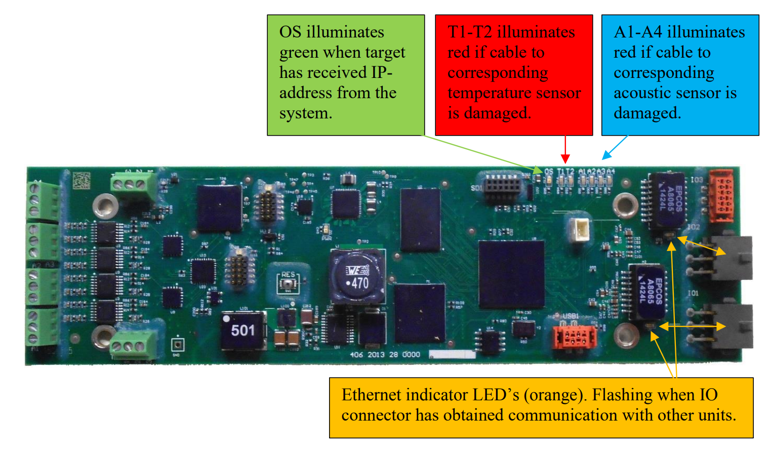
To simplify repairs, all upper sensor wirings are run on the outskirt of the target frame. In the case of a bullet or ricochet cutting a sensor cable, the target electronics will detect that something is wrong with the sensor and also provide warnings to the scoring system. Additionally the circuit board inside the target (the target electronics) will display sensor status by use of LEDs. This circuit board is accessible behind the service panel at the bottom of the target.
Sensor cables may be temporarily spliced with butt splices. However, as a permanent repair cables should be spliced by soldering and sealed with heat shrink tube - if sensor cable isn't replaced. Please also splice the un-isolated leader in the sensor cables.
Replacing sensors
In some cases it might be easier or necessary to replace the entire sensor with wiring harness.
The sensor wires are attached to their respective numbered terminal blocks according to the tables below:
| Connector No. | Attached sensor |
| A1 | Upper right acoustic sensor |
| A2 | Lower right acoustic sensor |
| A3 | Lower left acoustic sensor |
| A4 | Upper left acoustic sensor |
| T1 | Lower temperature sensor |
| T2 | Upper temperature sensor |
The teminal blocks are found at the left side of the board (green components at the image above). Teminal block A1 is the lower left, followed by A2, A3 and the A4 is the upper left block. Each connection point of each termainal block are individually numbered 1, 2 and 3.
For sensors A1-A4 the sensor cable is connected to the terminal blocks as follows:
| Wire | Connection point |
| Red | 1 |
| Black | 2 |
| Cable screen / Ground | 3 |
For sensor T2 the sensor cable is connected to its teminal block as follows:
| Wire | Connection point |
| White | 1 |
| Black | 2 |
| Cable screen / Ground | 3 |
For sensor T1 the sensor cable is connected to its terminal block as follows:
| Wire | Connection point |
| Red | 1 |
| Green | 2 |
| Yellow | 3 |
Replacing the upper acoustic sensors
If the upper sensors are to be replaced a section (corner) of the target rubber skin must be detached the target frame to access the sensor(s). We recommend accessing from the front of the target. The acoustic sensors are taped to an aluminum bracket that is screwed into the target frame.
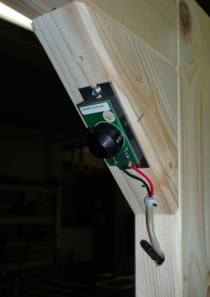 Upper right acoustic sensor mounted on aluminum bracket. The upper right temperature sensor is also visible.
Use the same screws and screw holes when replacing the sensor.
The temperature sensor is supposed to extend only 2-3 cm inside the target frame.
Replacing I/O cables
I/O cables are pre fabricated to specific lengths. The male and the female I/O cables are connected to the target electroniscs IO1 and IO2 box connectors at the right side of the board. Also, cable ground wires are screwed to the metal of which the target electronics is attached.


When ordering I/O cables make sure to choose the connector series fitting rest of the system. See exploaded view parts list at top of this user manual to find part numbers.
I/O cables are attached to target frame with cable clamps and a and some adhesive tape. Install the cables as the original cable harness. Get some cable ties before replacing cables, in addition to canvas tape.
I/O cables are always put in a loop inside target, to obtain maximum strain relief. Prevent loop from touching any nearby sensors by bending the loop in combination with using cable clips. Images below from different target models:
 |
 |
I/O cables should extend approximately 14cm from the underside of the target frame.

Replace target rubber skin
Picking off worn target rubber skin
Picking off target rubber skins
Worn target rubber skins are picked off target by following steps (general routine):
- Remove duct tape along edges of the worn target rubber skin.
- Consider marking the target frame (edges of existing target rubber skin) to easier add a new target rubber skin at later state (getting same tension).
- Remove staples along edges of the worn target rubber skin (flat screwdriver or staple remover needed, in addition to pliers).
- Unscrew the hinges of the service panel (screws above the service panel).
- Pull off service panel (still attached to target rubber skin and hinges).
- Turn the service panel back side up, and remove stables along the bottom of the target rubber skin.
- Unscrew the aluminium bar at the back of the service panel.
- Keep screws and aluminum bar for later assembly (to be reused).
- Dispose worn target rubber skin in a proper way.
Putting on new target rubber skin
Put new target rubber skin at target
Instructions below. Images are taken from different target models, but procedure is equal for different target models:
| 1 | Lie the service panel down flat on the base of the target with the hinges facing up. Centre the target rubber skin (sideways) over the hatch, so the rubber skin is extending 1cm below the bottom of the panel. |

|
| 2 | The target rubber skin is attached to the service panel by attaching the aluminium bar along the top of the panel. Use 4x20mm wood screws. Grip is improved by first adding contact adhesive on the rubber sheet and the aluminium bar. Consider marking the desired position of the aluminiumbar before adding glue. |

|
| 3 | If necessary, adjust the width of the rubber skin to prevent it from covering the hinges. Do not cut off more than necessary! |  |
| 4 | Pull the rubber skin lightly downwards and staple it to the bottom of the service panel with some staples. |  |
| 5 | Turn the inspection hatch and centre it sideways. It shall bear against the bottom of the target frame. Be careful with the sensors as they break easily. Attach the hinges at the inspection hatch to the target frame. |

|
| 6 | Tighten the target rubber skin and staple to the target frame. Start with the upper corners. Then tighten and staple sides and the top. Note! Electrical and pneumatic staplers exist. |

|
| 7 | Add a stripe of spray glue in the transition between the target rubber skin and the target frame. Let the glue dry and cover the glue with a stripe of canvas tape. |

|
| 8 | Cut a hole in the centre of the target rubber skin. Shape and diameter as specified below. Use a template to mark the cutting line(s), and please remember that the target rubber skin is stretched – so the hole gets bigger. |  |
This target model is supplied with a Ø35x55cm hole to the front target rubber skin.

The target may be used for a while without cutting a hole to the rear target rubber skin. However, when it get coin-sized holes, please make a round cut-out at center of the rear target rubber skin as well, to maintain accurate scoring. In this event, we suggest making an approximately Ø30cm hole.
Important notice!
Due to the wide cut-out of the front target rubber skin, in combination with the low profile of this target model, the front target rubber skin needs to be particularly tight when installed, to ensure that edges of the cut-out later will rest tight against the target rubber band.
Replace target rubber band
Replace rubber band
Worn rubber band is simply cut off by scissors. In this case, pay attention not to cut into the main target rubber skin.
New rubber band is installed as described below. The procedure must be done by two persons. Images below may not relate to this target model, but the installation procedure is equal to all target models:
| 1 | Put the rubber band slightly down (3-4cm) on top of the target. |  |
| 2 | Spraying soap water at the outer left and right side of the rubber band will make further operations easier. |  |
| 3 |
Twist the rubber band down and pull down/out until the rubber band get straight. It is important that both persons are synchronized and do the motions simultaneously.
|
 |
| 4 |
Again, twist the rubber band down and pull down/out until the rubber band covers the middle of the target. Adjust by pulling. There are probably marks or milling to the target frame, indicating where the rubber band is supposed to be.
|
 |
| 5 |
The end result.
|
 |
Positioning
It is very important that the rubber band is covering any cut-outs of the main target rubber skin - with good margins (2-3cm).
Protecting the target
Lower part of the target can, and should be, protected against stray bullets - to prevent costly repairs. Most electronics are hidden and partially protected behind the target service panel. In this respect, protection against stray bullets is mainly about protecting the target from bottom to the top of the service panel.

This target model is typically used as a running target. Protection is then typically done by a knee wall, in front of the target along its path.
Leave space for access
It is recommended that that a distance of 1m be created between the knee wall and the target, to possibly access the target front and service panel. However, if the target passes the knee wall at some point along the path, and target front and service panel can be accessed to the side of the knee wall, the knee wall is better close to the target (usually create less ricochet damages to the target).