Introduction OpticScore eScore
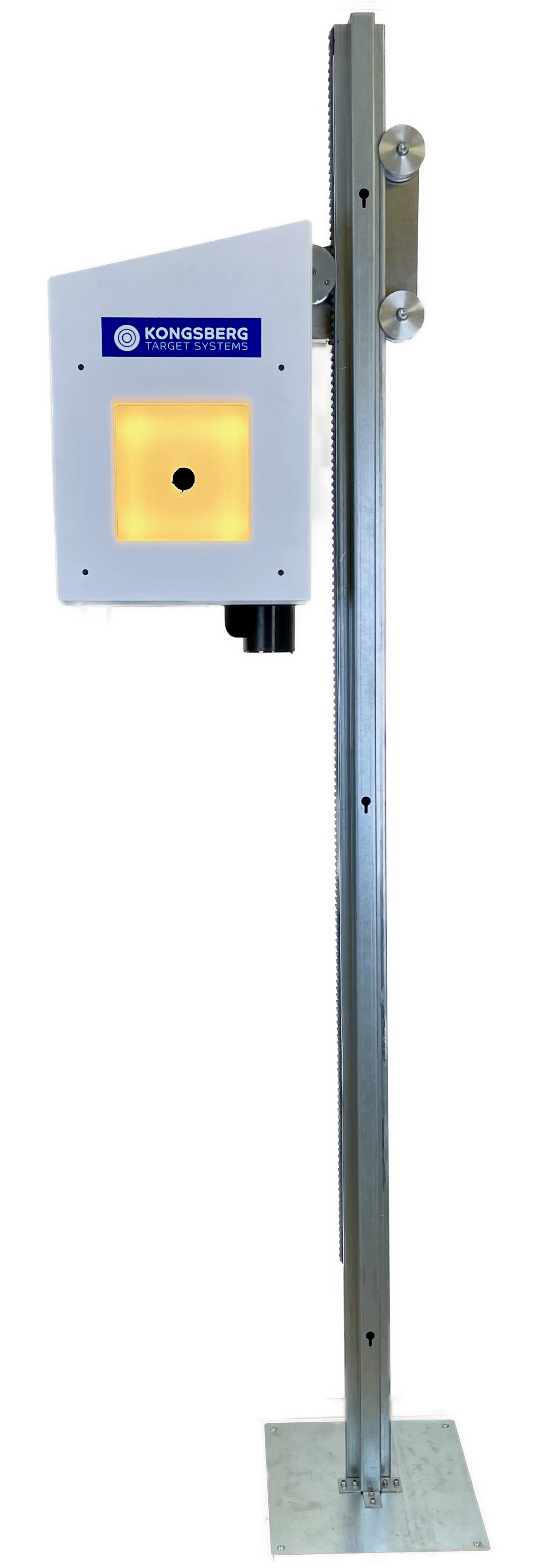
The eScore OpticScore target is a next generation electronic target system with optical detection technology. Cameras inside the target precisely detects the bullet. The target is recommended for indoor ranges and for use with air rifles, air pistols and caliber .22LR rifle options are available. The target can be delivered with a target lift, allowing for different shooting heights (kneeling, standing and prone positions). The LED illumination can be adjusted by the shooter providing optimal brightness and color scheme for any shooting conditions and personal preferences.
Features for eScore OpticScore
Precise detection - Detection frame has an ISSF Phase 1 approval.
Suitable for short range (10 - 15 m) .22LR and air gun.
Small size, quick setup
Wide range of target scoring definitions and mask targets available
Easy to replace mask target
Low maintenance
Target lift available
Adjustable illumination (intensity and color scheme)
Technical Specifications and dimensions
| Temperature range | 0 to +40 °C |
| Weight | 3.5 kg (Target Only) 8 kg (Target with protection plate) 13.5 kg (Target Lift) |
| Power consumption | ~ 17 W @ 24 VDC (With illumination at max) ~ 50 W @ 24 VDC (Target lift moving upwards, illumination on) |
| Approved Calibers | 4.5mm Air Guns and .22LR rifle |
| Recommended use | 10-15 m air pistol / air rifle 10-15 m .22LR Rifle |
| Recommended Operating Voltage | Typ 24 V (May operate in 12V-48V range) |
Dimensions
| A: 470 mm | 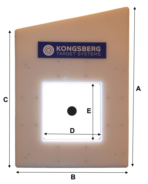 |
|
| B: 400 mm | ||
| C: 330 mm | ||
| D: 170 mm | ||
| E: 170 mm |
eScore OpticScore exploded view and partslist
Exploded view Below is an exploded view of the common components used in the eSco...
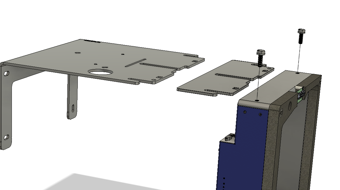
Exploded view
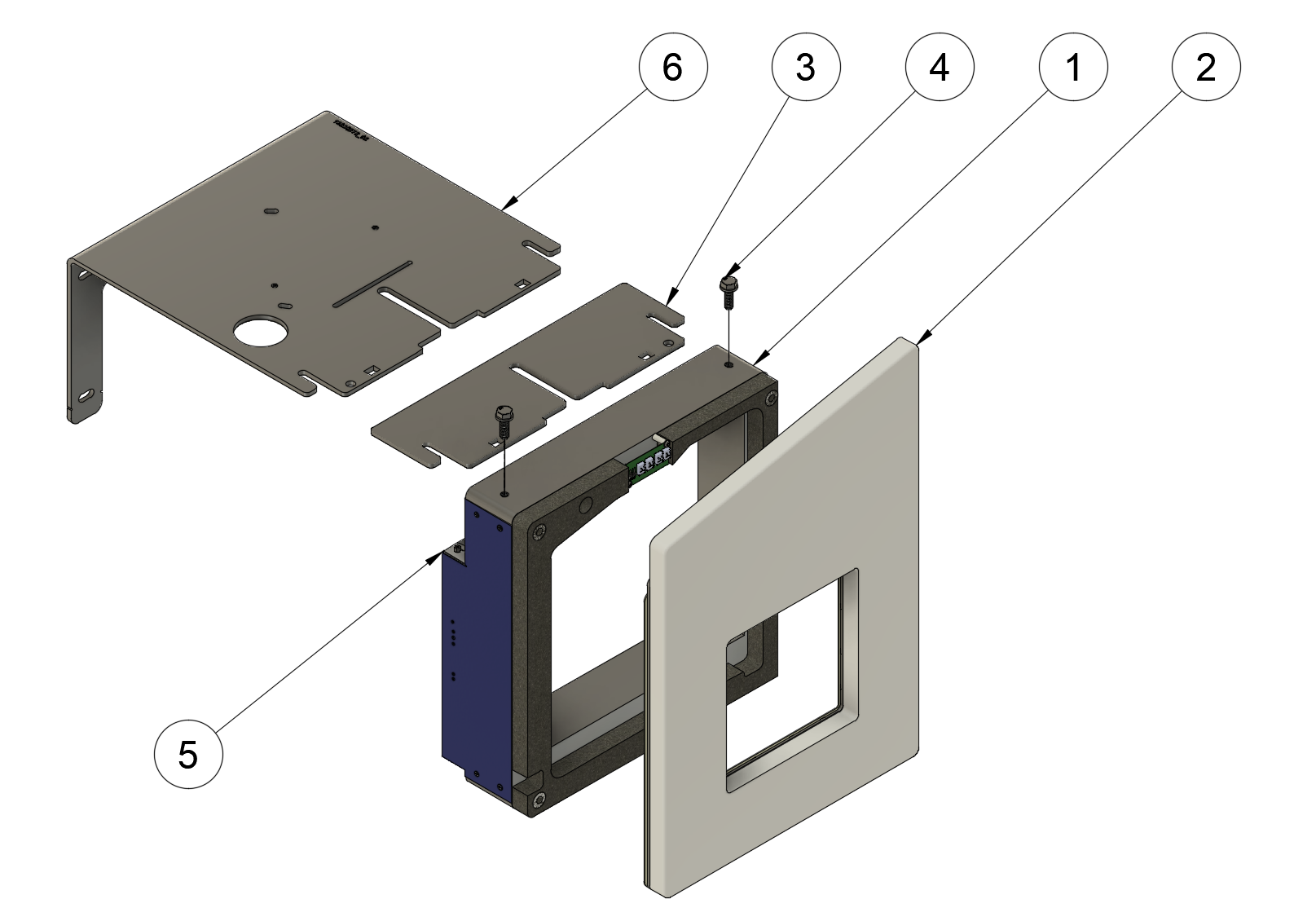
Below is an exploded view of the common components used in the eScore OpticScore target
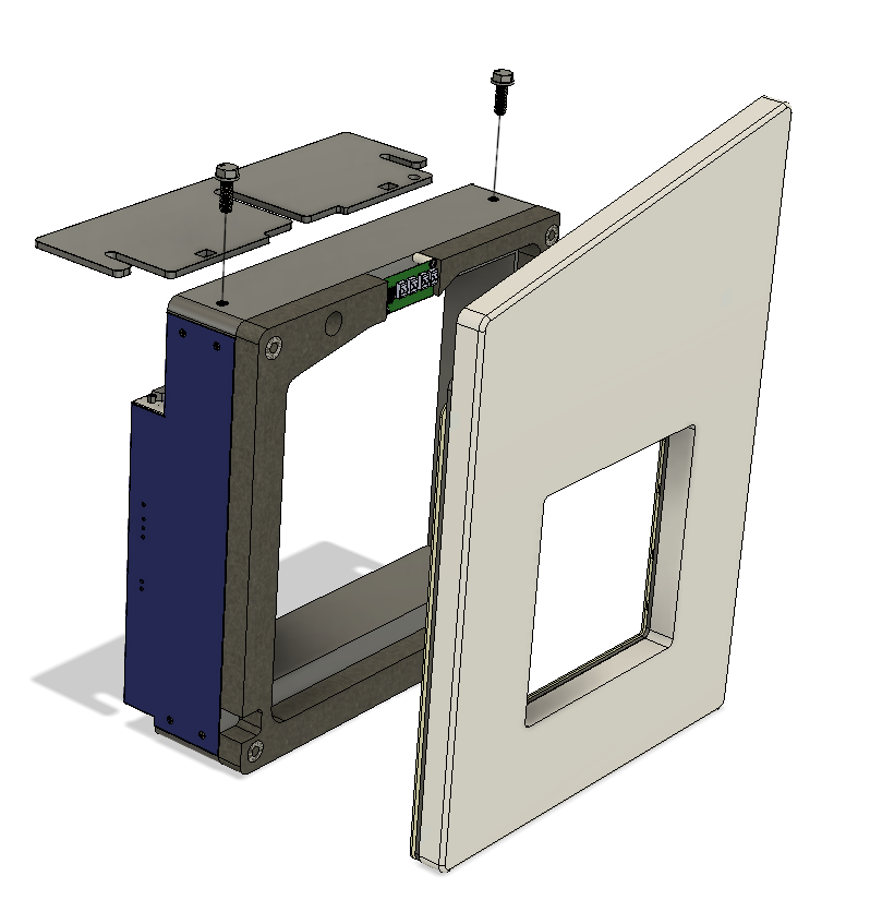
Part list
| ID | Description |
| 1 | eScore OpticScore Target |
| 2 | Protection plate with illumination |
| 3 | Illumination bracket |
| 4 | Mounting screws and washer (M8) |
| 5 | eScore OpticScore Target electronics housing (wiring not shown)- options with different connectors are available |
| 6 | Optional: Wall mount / bullet catcher bracket |
Available mask targets for OpticScore
Available mask targets for OpticScore
The OpticScore target can be fitted with different mask targets:
| KTS part number: | Name | Spot size |
| 97020797 | ISSF 10m air rifle | Ø 30.5mm |
| 97020798 | ISSF 10m air pistol | Ø 59.5mm |
| 97020810 | DFS 15m rifle | Ø 38mm |
| 97020848 | NSF 15m rifle | Ø 34.2mm |
| 97020879 | DGI 15m air rifle | Ø 42.75mm |
| 97020880 | DGI 15m pistol | Ø 100mm |
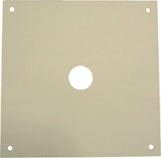
The target may also be fitted with a black cardboard backer / witness plate (KTS part no: 97020801).

Maintenance requirements for eScore OpticScore
While the eScore OpticScore target is virtually maintenance free - the environment on and around the target line can be challenging in terms of debris from bullets and the paper mask targets. This introduces some minor maintenance that should be done to preserve optimal accuracy for this optical target.
Please note: Whenever handling the OpticScore target, take great care NOT to touch the mirrors or glass in the target. Finger prints, scratches or other damages to the optical detection surfaces are not accepted as warranty claims. Observe and follow the recommendations related to the cleaning and handling procedures in this chapter closely, including NOT to blow dust and paper residue out of the target manually (by mouth).
Replacing mask target
There is a number of mask targets available for this target. Whenever it is shot out (hits outside the "black" area leaves a bullet hole) - or the user wants to change the mask target to another target definition.
Tools necessary: None
Equipment necessary: New target, microfiber cloth
Step 1:
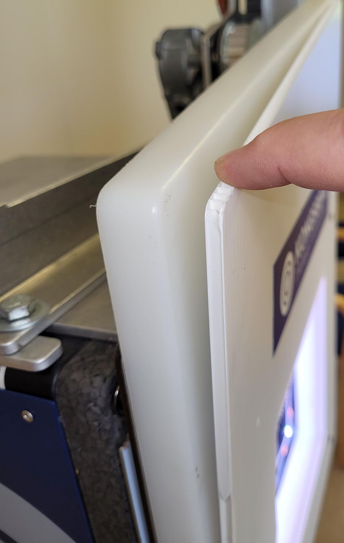
Take off the protection plate. The protection plate is hanging on the Illumination bracket or Bullet catcher/wall mount bracket with two pan head M8 screws secured in the protection plate. Simply tilt the bottom of the protection plate away from the target until the magnets releases and then lift up the protection plate.
Ensure that the components at the back of the protection plate are not damaged by placing it on a flat and stable surface while working on the target.
The below video shows the recommended motions for disassembling the protection plate.
Step 2:
Remove the old mask target and recycle it
Step 3:
Remove any debris if necessary - see next chapter for guidelines
Step 4:
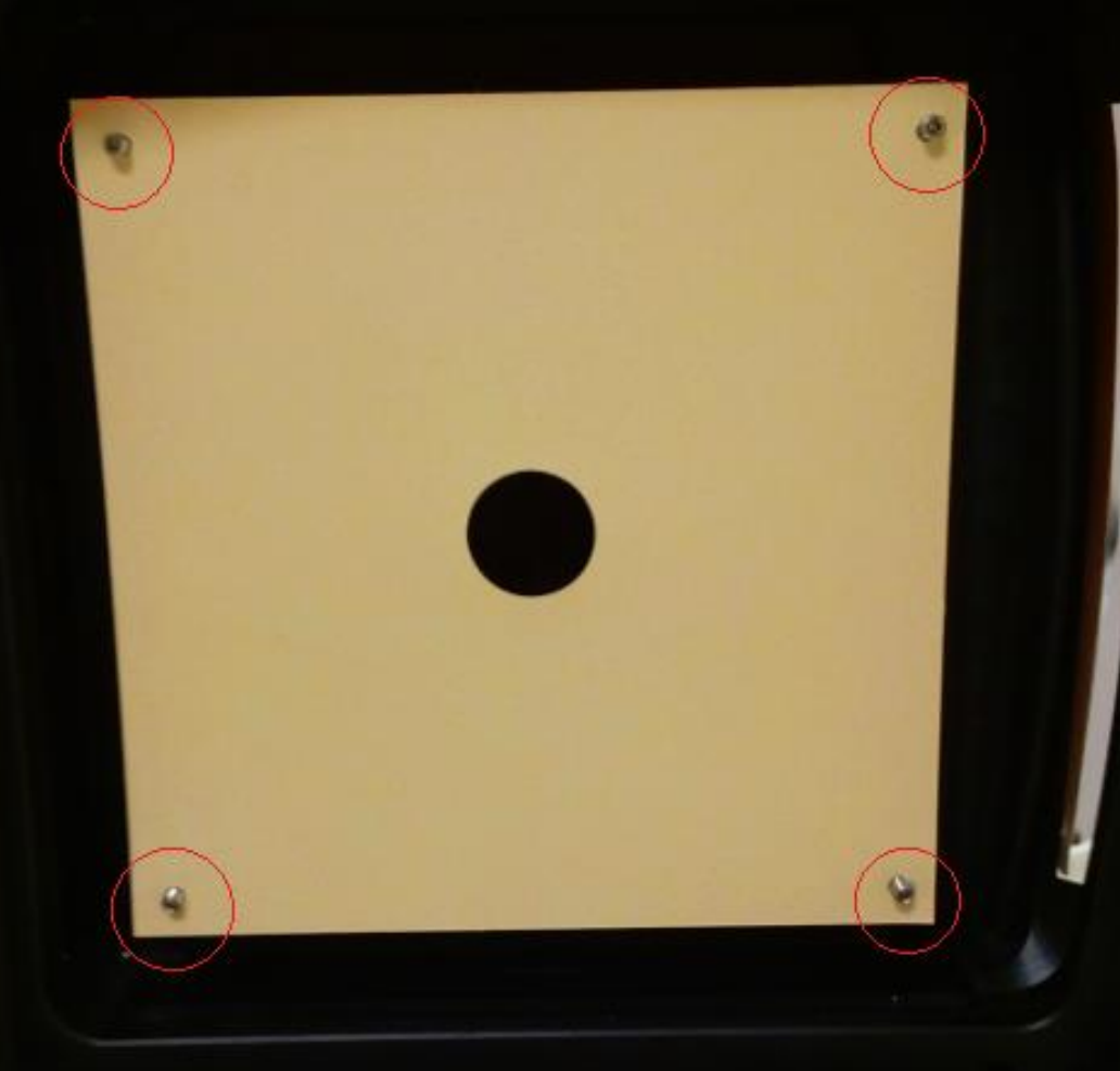
Insert the new mask target from the front of the target. Use the four holes in the corners of the new mask target and put it onto the four screws inside the target. The screws are made a bit flexible to be able to strighten the mask target.
It is outmost important that the mask target is completely stright after installation. A bent mask target might interfere with the optical measuring field.
If using a black background or verification paper
A new background / verification paper can be installed by sliding it in/out from the backside of the target as illustrated: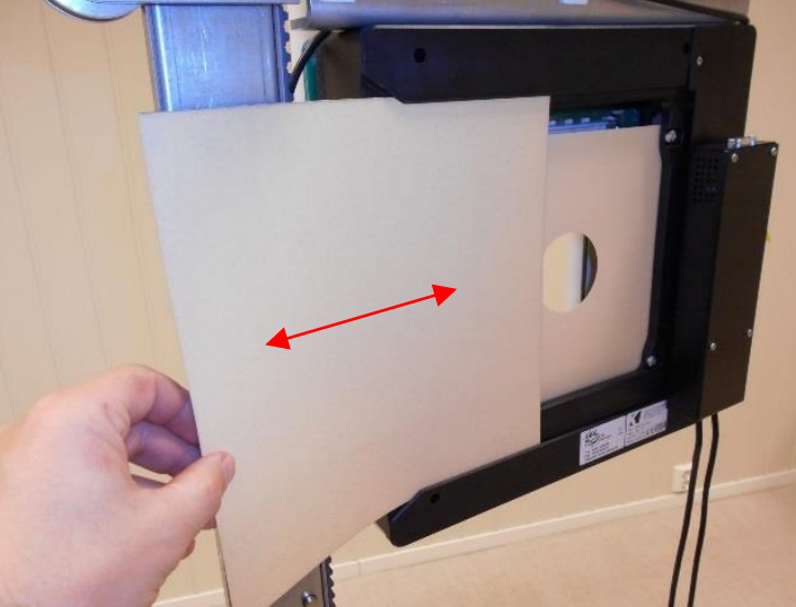
Step 5:
Reinstall the protection plate. Take care not to damage the components at the back of it! See the below video for an illustration on how to properly install the plate.
Verify that the illumination lights up up after installation of target front!
This can take some seconds after power-on. If the illumination has not lit up after 30 seconds, verify that there is power on the target by inspecting the OS LED on the side of the target. If power is on and illumination is off, try squeezing the protection plate against the target frame.
Critical surfaces, removing debris or particles
Warning
Take care not to damage the mirrors or glass plates inside the target! Fingerprints or scratches will degrade accuracy!
Any paper particles or other debris on the surfaces inside the target have the potential to degrade accuracy. It is therefore recommended to remove debris when replacing sighting reference. This should be done using lightly pressurized air.
Warning
Compressor pressurized air should not be used, or blowing air manually should NOT be done! This may leave residues of compressor oil or saliva which will corrode on the mirror surfaces.
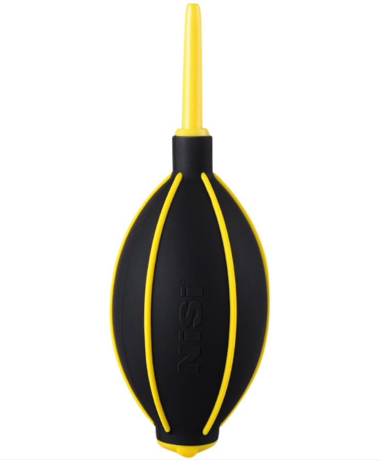
A camera lens air blower should be used. It does not leave residues or have too high pressure:
The mirrors are silver plated. Cleaning of the mirrors should only be done when needed to preserve their properties. Each cleaning will introduce minor wear and tear on the mirror surface.
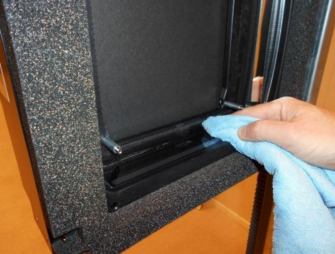
When cleaning the mirrors and glass surfaces, the following should be considered:
- Gently remove paper particles by using air (see above tool)
- Using a clean microfiber cloth, gently wipe away remaining residue
- If necessary a damp microfiber cloth can be used, but moisture residue on the surfaces must be avoided.
Visible corrosion on the mirror surfaces
If corrosion or other contamination is visible on the mirror, a NON ABRASIVE silver care creme can be used to polish it. Show great care and do not use excessive force!
Be sure to follow the procedures above, and be sure to clean up all residues after use.
KTS can supply or recommend a suitable silver care product upon request.
Cleaning or treatment of mirrors are not recommended unless contamination is visible.
Storage requirements
Storage of OpticScore target
The eScore OpticScore target must be stored in a clean and dry environment (<50% humidity) above 10 °C. If there is a high degree of particles in the air or environment in storage, the target should be covered so that the glass and mirror surfaces in the target is not exposed to a high degree of contamination.
Add on equipment
There is a number of additional equipment that can be ordered with the OpticScore - eScore target. They are listed here:
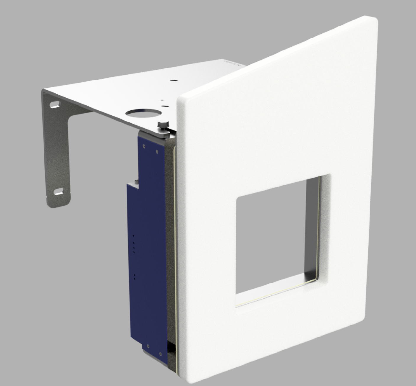
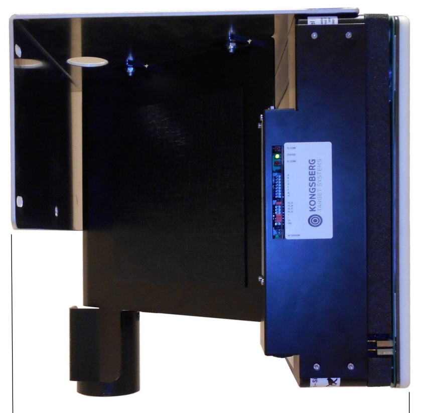
Wall mount / bullet catcher bracket
The eScore opticScore have a wall mounting bracket available, that also may act as a mount for the bullet catcher for air guns. The bracket have a centerline mark that aligns with the center of the target (in height). This is helpful when aligning targets with a specific height on the range. The bracket comes with four holes at the back, for screws that can be used to fix target to wall. Use a bubble leveler or similar when mounting the bracket to the wall to ensure horizontal axis alignment.
There must be a bullet catcher behind the wall, to utilize wall mount without air gun bulletcatcher.
Tip!
Fasten the wall mount bracket to wall, before attaching target to the bracket.
Please note that this bracket is always used when utilizing the airgun bullet catcher, even if the target is not mounted to a wall (i.e. target used with target lift).
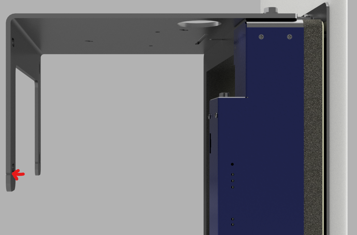
The wall mount/bullet catcher bracket is attaced to the target in following way:
- Remove the Protection plate (See the maintenance chapter for guidance)
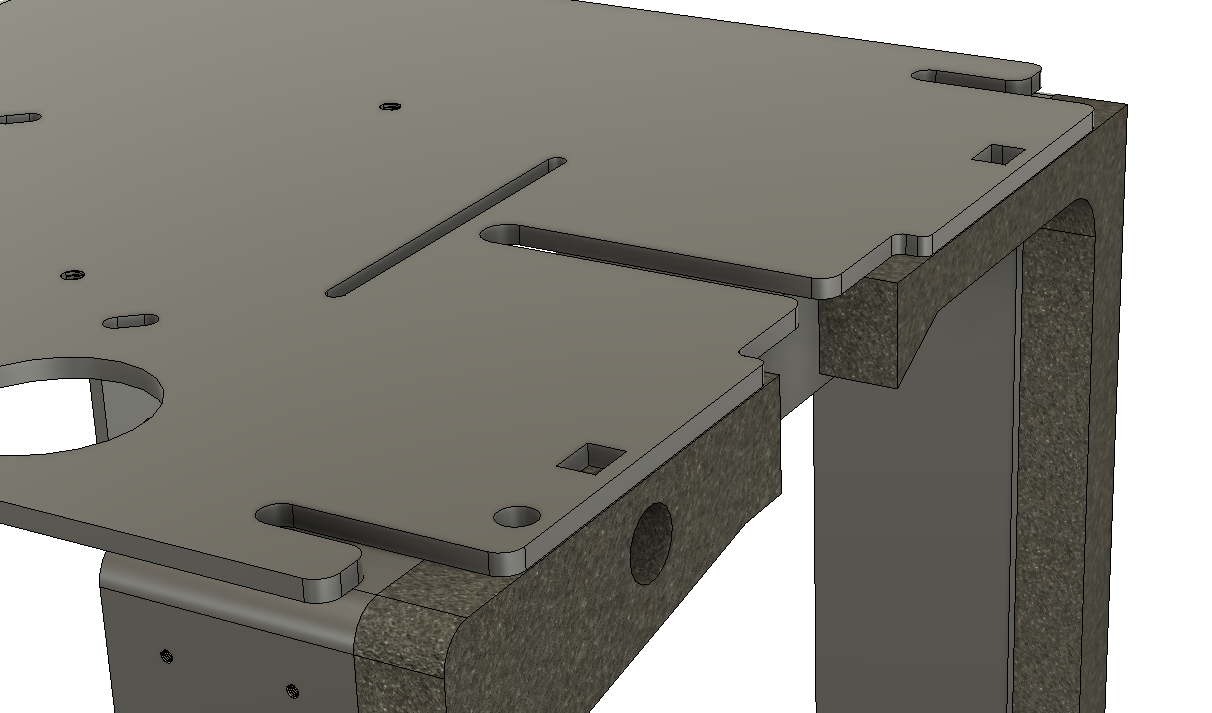
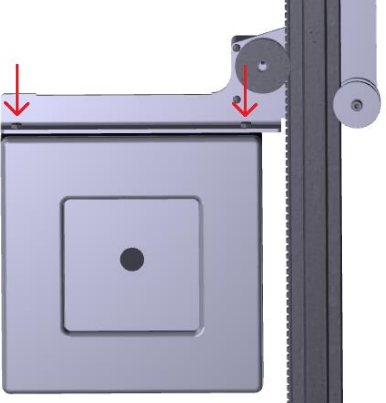
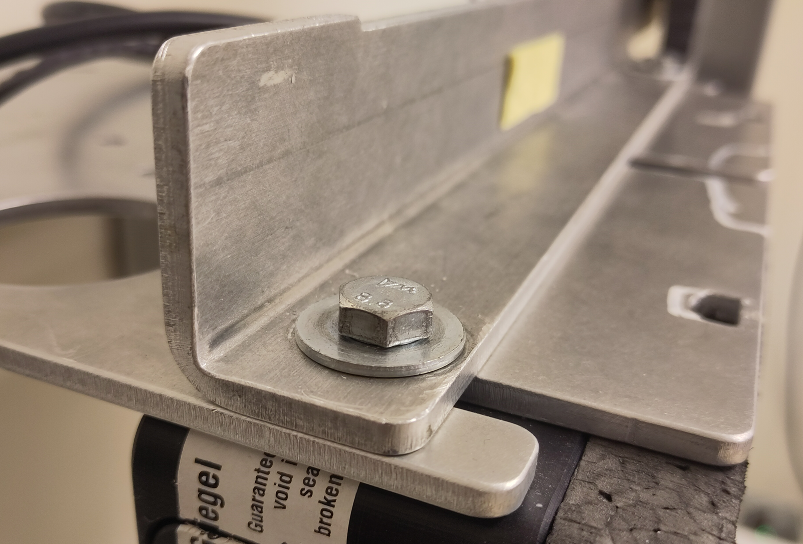
- Slightly loosen the 2x M8 Hex Screws on top of the target.
Note that if the target is currently fixed to a target lift or wall mount bracket, these bolts must not be loosened all the way! This may cause the target to fall down and break.
- Swap the illumination bracket with the wall mount bracket - ensure that the washers are placed on top of the bracket and not underneath
- Tighten the screws (Do not use excessive force!)
Note!
Ensure that the target is pushed all the way into the groove of the bracket.
- Reattach the Protection plate (See maintenance chapter for guidance).
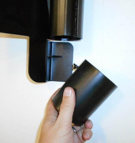
4.5 mm air gun bullet catcher
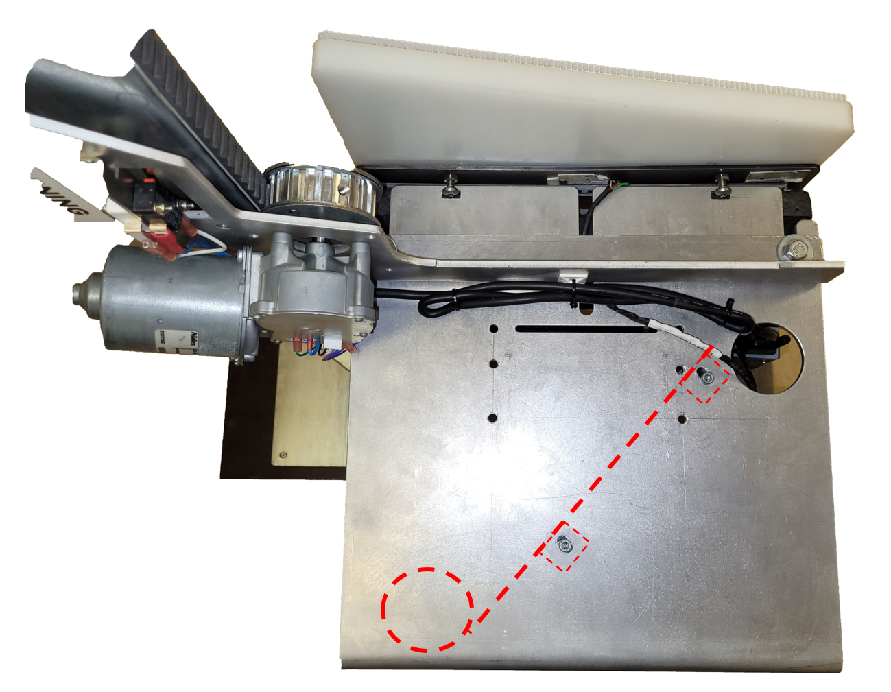
An optional air gun bullet catcher is available, KTS Partnumber 33 07 004 - note that you must have the wall mount/bullet catcher bracket (KTS part no 13020272) to be able to correctly mount the bullet catcher to the target. The bracket may also be also used with target lifts. Bullet catcher must be attached to the bracket. Use the supplied nuts and bolts, as shown at illustrations below.
Warning!
This bullet catcher must NOT be shot at with any other bullets than air gun pellets in caliber 4.5 mm
Note that the target used in photo above is another target model, but the image illustrate how the bullet catcher is attached to the bracket. Image below also illustrate how the bullet catcher is positioned inside the bracket (red dotted lines).
Airgun ricochet protection plate
Air gun pellets may bounce back against shooter position if it misses the scoring area and hit target protection plate. To prevent this, a ricochet protection plate (KTS part no 97020813) may be attached to the target protection plate. It is attached by four platic buttons (KTS part no 1507002).

This plate can not handle a finite number of shots, and may have to be raplaced when outer surface is degraded. Pellets are captured inside outer surface of the plate
Target lift
eScore OpticScore Target Lift
Target lifts are available for the opticScore eScore target. Some assembly is required on the range on first time use and this is described here.
Assembly instructions
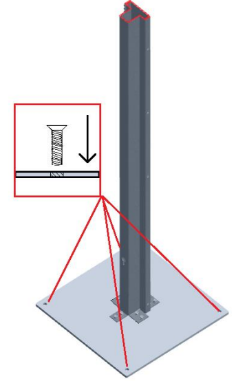
| Mount the bottom plate to the lifter spine with the included nuts, bolts and washers | 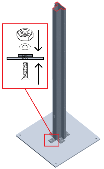 |
|
Mount the bottom plate to the floor (or other suitable platform) with appropriate fasteners for the selected material Warning!This has to be done prior to mounting the target to the target lift!
|
 |
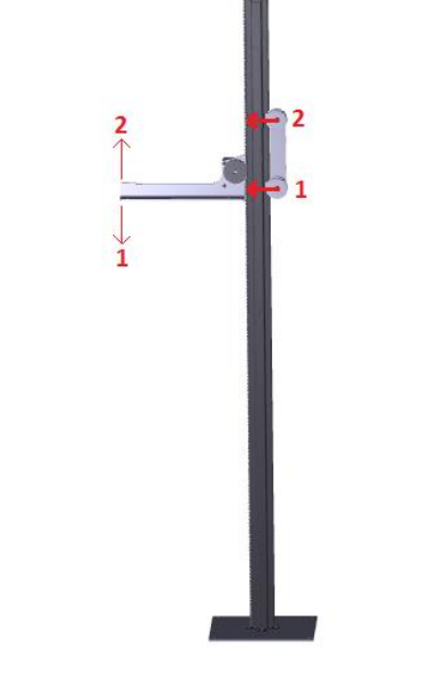
| Mount the end-stop bracket with two screws and spring-washers. Use the upper position, NOT the lower. | 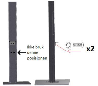 |
|
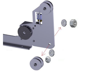
Remove the lower support wheel from the lift bracket. Assembly infoRemember the orientation of the conical washer that is assembled next to the bearing inside the support wheel. This washer must be inserted in the same orientation and the same sequence in relation to the other washers
|
 |
|
Rotate the lifter bracket and insert it onto the lifter spine. Rotate it counter clockwise so that the gear and support wheels support the lifter bracket. Assembly infoMount the lower support wheel, but do not tighten the screws (Yet)
|
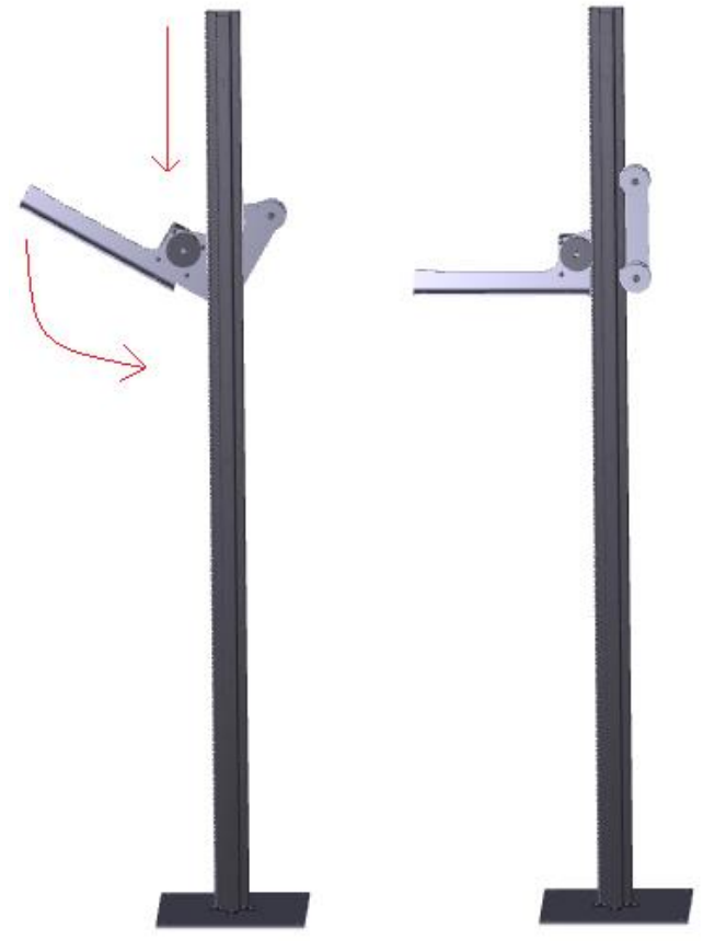 |
The bracket shall now be approximately 90 degrees in relation to the spine. Adjust the support wheels as appropriate if necessary. Assembly warningDo not over-tighten the screws on the support wheels as the bearings might be damaged.
Assembly tipIt is required to be two persons while performing this step.
|
 |
|
Install end-stop triggers at the lifter spine
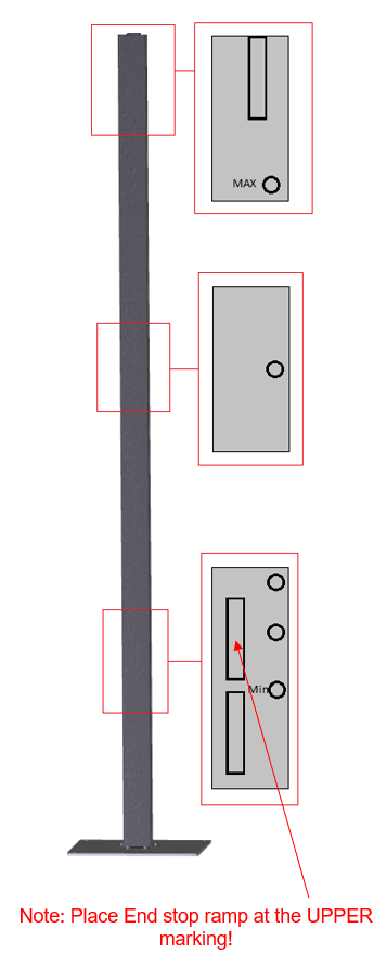
Remove the protection on the two-sided tape on the back of the end-stop triggers. (Two in total) 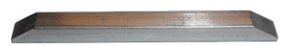 Tape the triggers to the rectangular marks at the the lifter spine indicated by the drawing to the right. One at top of the spine, and two at the bottom. Don't mind the round marks. Please noteNote that on the lower end of the lifter spine, there are two rectangular marks. Use the upper one, indicated at the drawing!
|
 |
| This figure shows the end-stop triggers and bracket in place. Don't mind the small circles. | 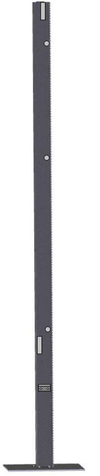 |
|
The target is now joined with the lifter bracket by the use of the two M8 bolts and washers (at top of target). Leave a small gap between the target frame and lifter bracket.
If the airgun bulletcatcher is used (thus using the bullet catcher bracket), then replace the supplied illumination bracket with the bullet catcher bracket in the above mentioned gap. Push it all way forward, until it rests against the screws.
Else, keep the illumination bracket in the mentioned gap. Push it all way forward, until it rests against the screws.
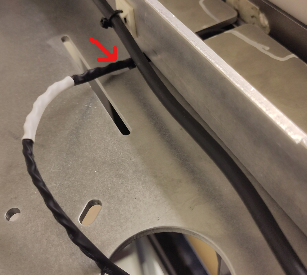
Note!Ensure that the Illumination cable is placed in the groove in the bullet catcher / illumination bracket. Tighten the two screws at the top of the target, that joins all brackets and target together. Do NOT overtighten these screws as the target will be damaged. |
   |
|
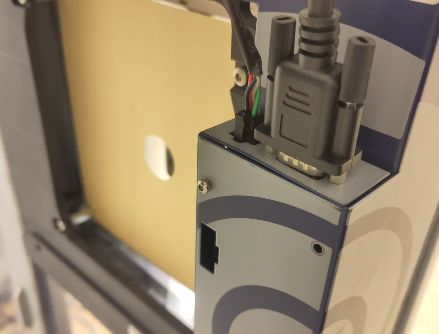
The cable from the lifter bracket motor is connected to the opticScore target. The illumination cable is also connected to the target. Image to the right shows both cables connected. |
|
Target lift ricochet protection
KTS part no 117 0097 44 0024.
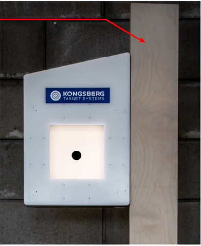
The product is covering the Lifter pole. Only used when shooting with cal .22LR. This product is working as a formal ricochet protection, and is also reducing damages to the Lifter pole if hit by stray shots.
The Ricochet protection is just hung at the keyholes on the front side of the Lifter pole. First assembly includes mounting of the three provided screws to the back of the Ricochet protection. There are pre-made holes for the screws.
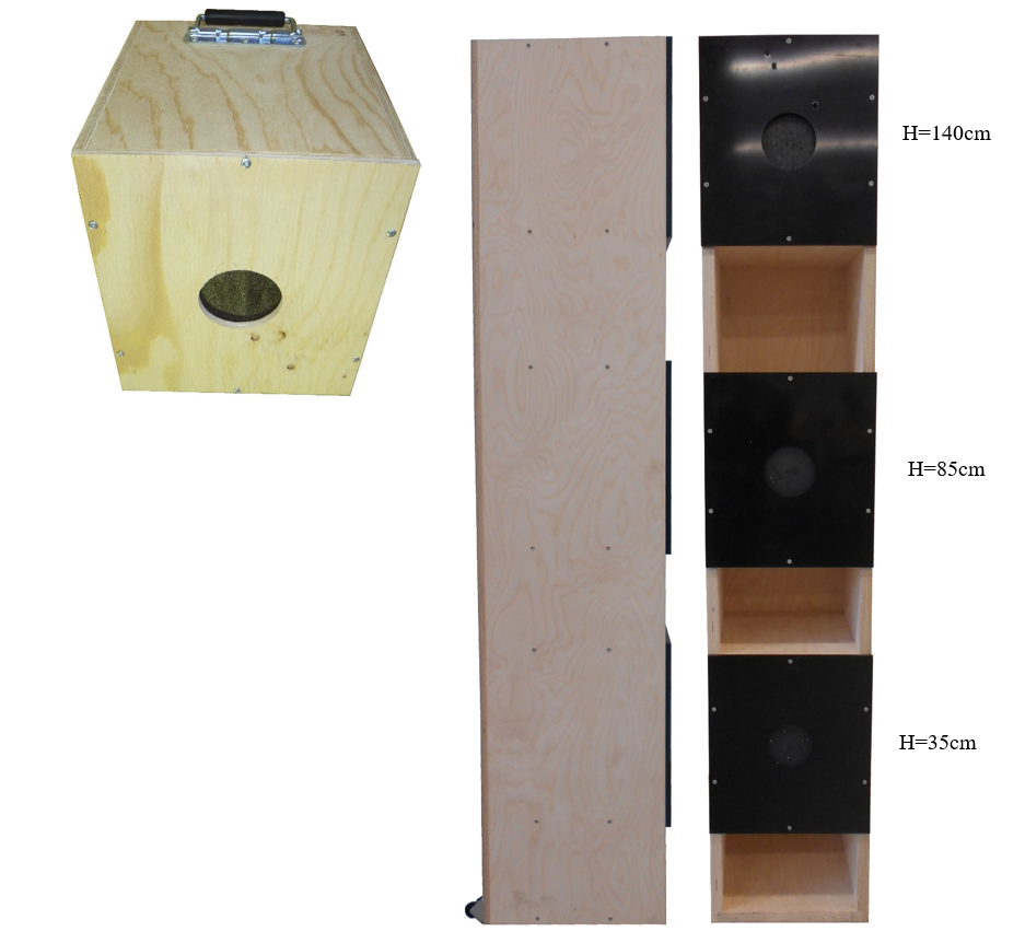
Rubber granule bullet catchers
Rubber granule bullet catchers (KTS part no 107 0097 24 0042) and Rubber granule bullet catchers for 3-position shooting (KTS part no 107 0097 24 0049) also exist. These bulletcatchers are mainly intended for kal .22LR bullets. They should not be used for more powerful calibres.