
Introduction to the H4D
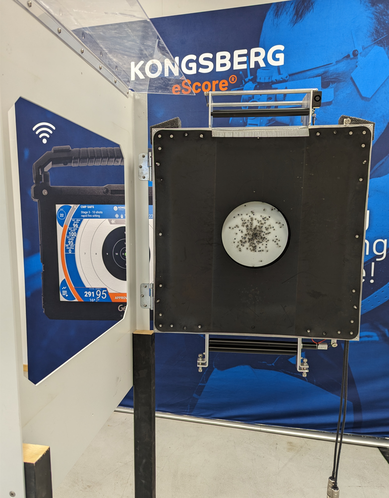
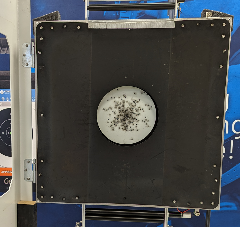
The H4D eScore target is a next generation electronic target based on acoustic sensors. It works with subsonic and supersonic ammunition and is designed to be used at distances of 25 - 100m (yd). Typical use is ISSF 50m rifle and ISSF related pistol shooting at 25 and 50m.
Features of the H4D target
- 4 acoustic sensors, one in each corner of the target.
- Latest eScore target electronics, with all signals fully processed in the digital domain.
- Automatic sensor input sensitivity adjustments for different calibers
- Automatic rubber belt feeding length processes fully automated
- BIT (Built In Test) running continuously.
- All electronic and vital parts fully protected by armor.
- Several mounting options.
- Base armor suitable for .22LR is standard
- Additional armor and protection for higher energy projectiles optional.
- Guide pin design allows swift and precise change of aiming mark.
- Can be used with subsonic projectiles like .22LR rifle and pistol calibers from .22LR to high energy pistol calibers.
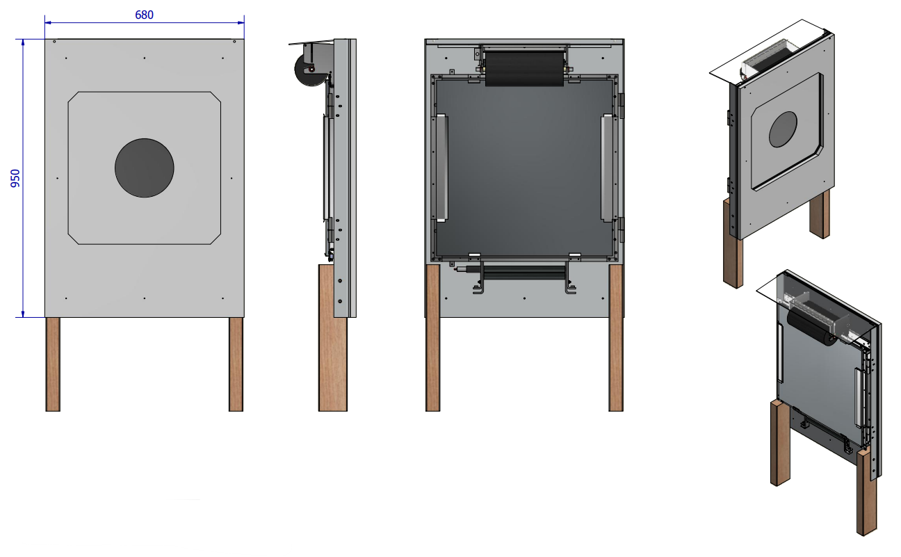
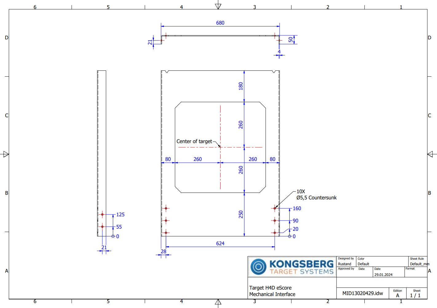
Technical specifications and dimensions
Width |
680mm |
 |
|
Height Excluding legs and optional pistol light mirror Legs are show as illustration only |
950mm |
|
Depth, with base armor |
205mm |
| Operating Temperature | -30 to +60 °C |
| Operating and storage humidity | 10 - 95% non condensing |
| Weight | ~ 30 kg (excluding extra armor) |
| Power consumption | ~ 8 W @ 24 VDC |
| Calibers | Subsonic and supersonic projectiles from .22LR to full bore pistol. |
Installation
Installation of the target at the range
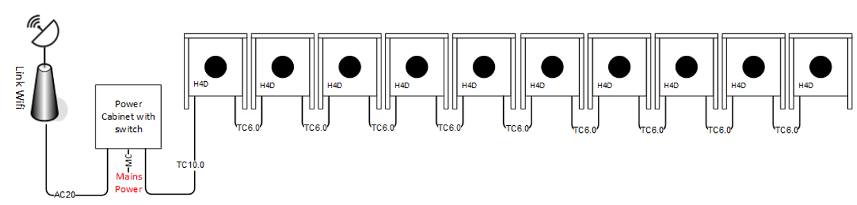
The H4D eScore targets use the typical eScore target connection topology with input and output connectors at each target. This enables a very easy installation by simply daisy chaining the targets requiring a very minimum of cables and connectors.
On a new system delivered from KTS, the lane numbers has already been set, and the targets are labelled clearly. Changing the lane numbers can be done through the eHub interface if needed.
Maximum number of targets in one chain is 10 targets.
Typical connection example for a 10 lane system:
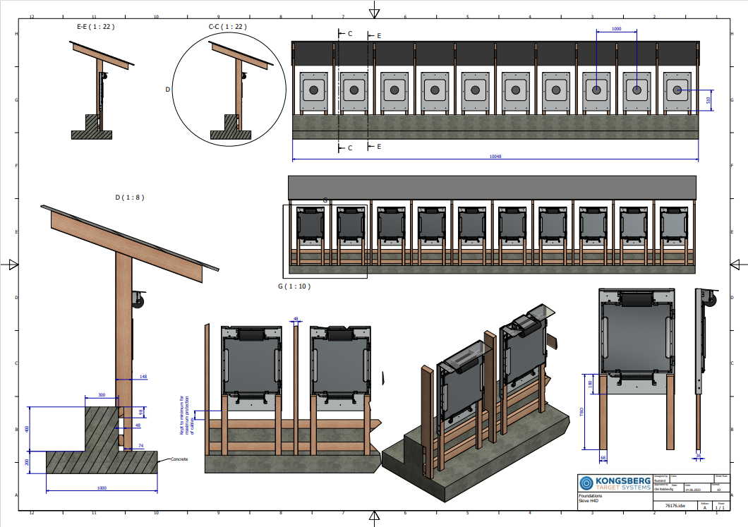
The mechanical construction of the target relies on the base armor to hold the target in position. The base armor has a number of attachment holes in the lower part for attaching the steel to whatever type of material and construction is used on the range. Important: To enable use and easy access when maintaining the target, a minimum open space of 80 cm behind the target is recommended. This is to be able to swing the target frame open during maintenance, in addition to provide space for personnel for easy access.
The H4D is designed to be installed under a covered target line - avoiding rain and snow reaching the target directly.
Example of a covered target line below. Note the protection between each target to avoid ricochets or splash from projectiles to damage the side of the neighboring targets:
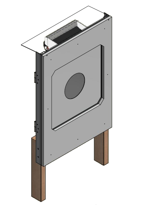
Mechanical details of the base armor:
The target base armor has hinges (pin) installed. The target frame assembly has mated hinges, simply lift the target frame in place after installing the base armor.
Optional equipment
Additional armor or ricochet protection
The base armor of the H4D is suitable for .22LR rounds, and no further protection of the target is necessary. If higher energy rounds are expected, or local regulations require ricochet protection, additional protection can easily be added.
| The additional protection has bolts used as hooks to mate to notches on the base armor top. Example to the right for a PEHD ricochet protection plate | 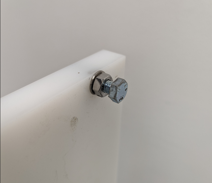 |
| A combined ricochet protection and extra armor is shown on the picture to the right. Simply hung on the base armor. | 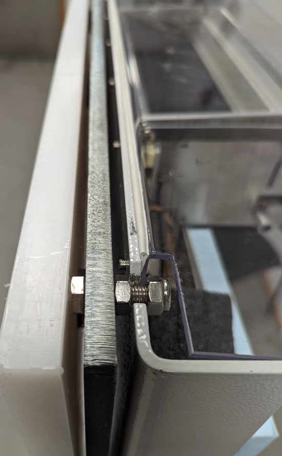 |
Routine maintenance
Installing or changing the front and rear rubber skin
The front and rear main rubber skin is held in place by hooking the rubber on screw heads on the target frame. Start with the attachment points up/down and left/right, and work your way out towards each corner. The process is equal for the front and rear rubber skin. Finish with the outer corners.
| Place the hole in the rubber skin over the screw head, and pull outwards from the center of the target. | 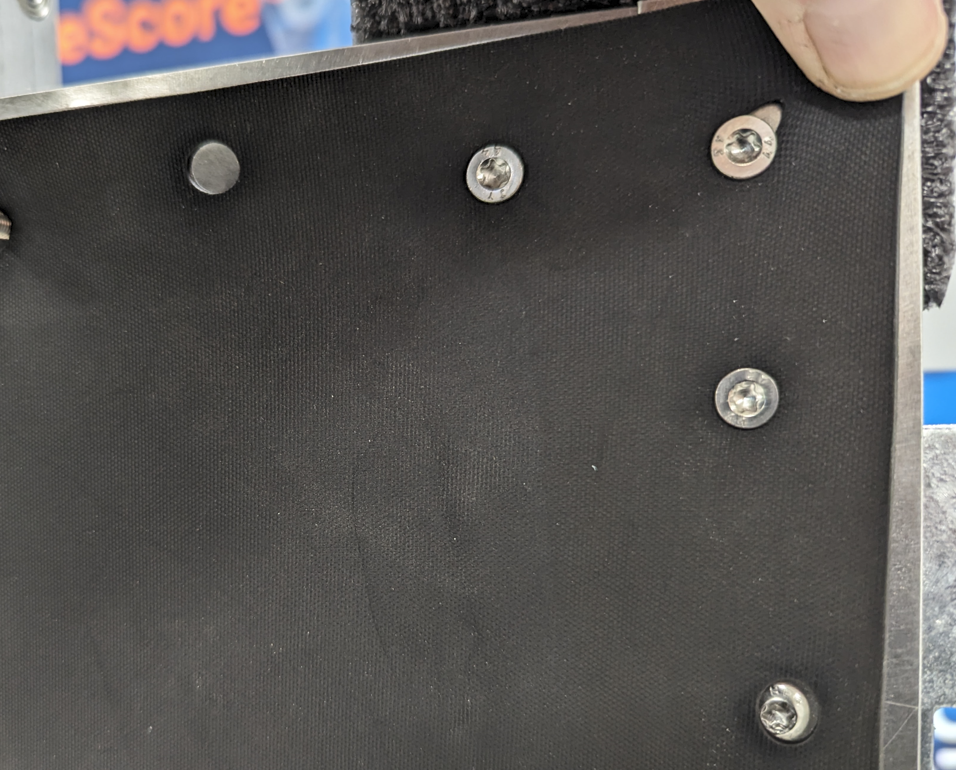 |
| Let the pull go and at the same time let the rubber “hook” under the screw head. | 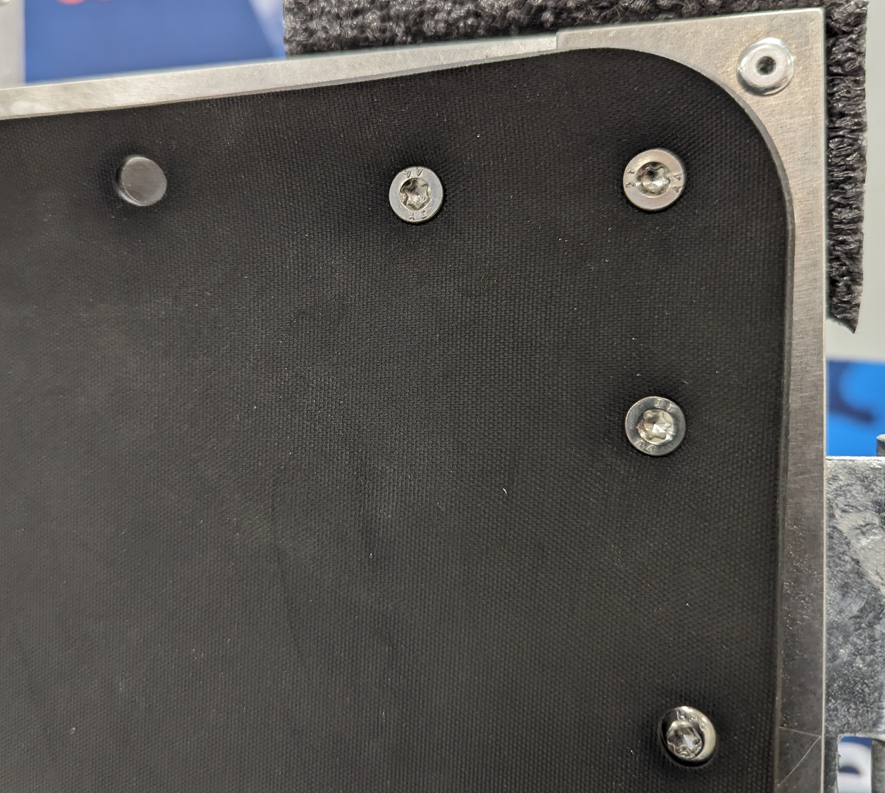 |
|
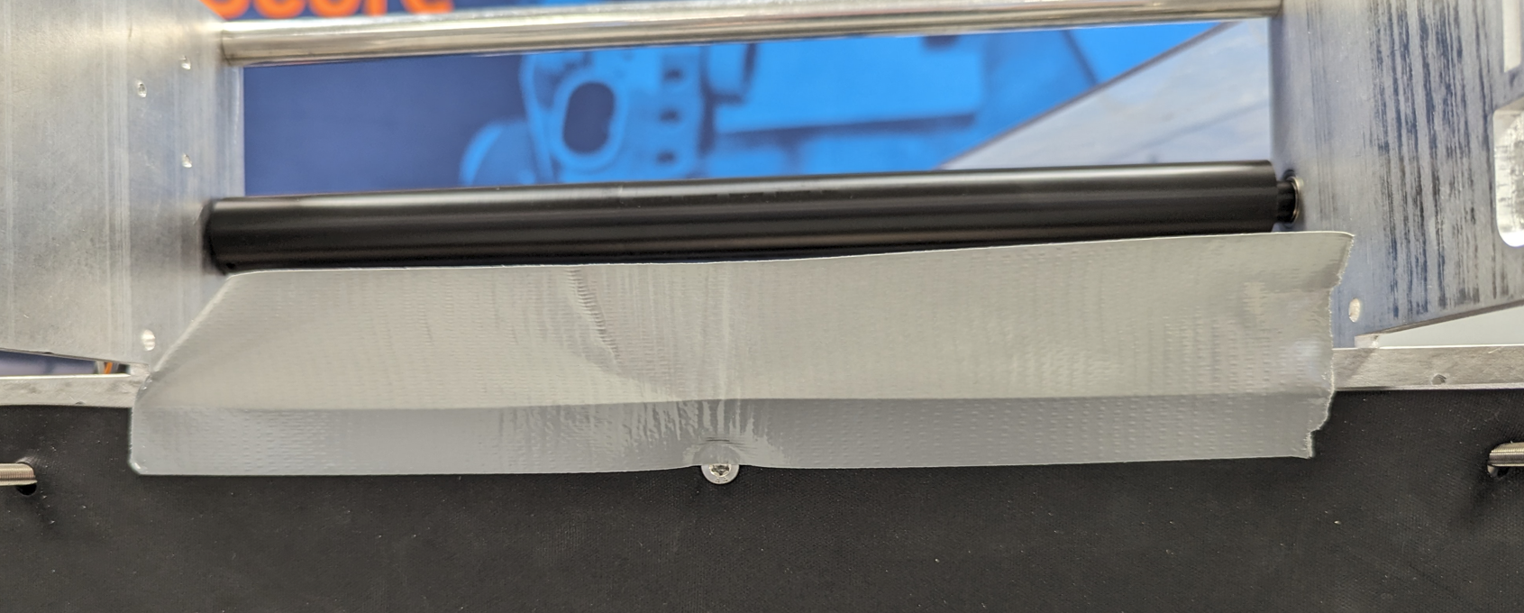
For both the front and rear rubber skin:
Tape the top part of the main rubber skin to the target frame using duct tape. Make sure that the tape adheres well to the rubber as shown on the picture. |
 |
|
Fold the tape over the target frame, and make sure it secures the rubber close to the target frame.
The tape prevents the rubber roll to hook to the rubber skin edge and prevent proper rubber feeding. |
 |
| Removal is the reverse of installation. Make sure to remove potential rests of tape on the target frame. | |
|
The frequency of changing the main rubber skin depends on calibers used and average group size. It is important to change the main rubbers before:
- The edge of the cut out hole loose integrity (gets too perforated). It should NEVER be loose parts of the main rubber skin “hanging” into the target.
- The rubber skin, especially outside the area normally not covered by the rubber band gets perforated to a level where you can see through the holes.
The main rubber skin should always feel tight and secure on the target frame.
The purpose of the main rubber skins, together with the rubber band, is to create a space for the acoustic sensors acoustically isolated from the surrounding. |
 |
Installing or changing the rear temperature shield
The rear temperature shield is held in place with screws on the target frame, and secured in place using wing nuts.
| Place the temperature shield on the back of the target. Keep the cut out part on the top of the target, it creates space for the rubber roll. | 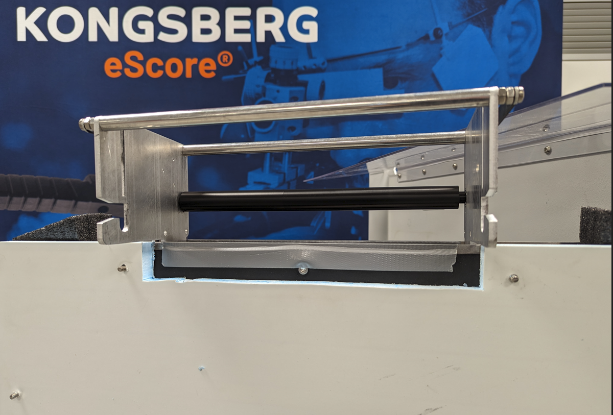 |
| Put the washers on the studs, and tighten the wing nuts without compressing the temperature shield too much. | 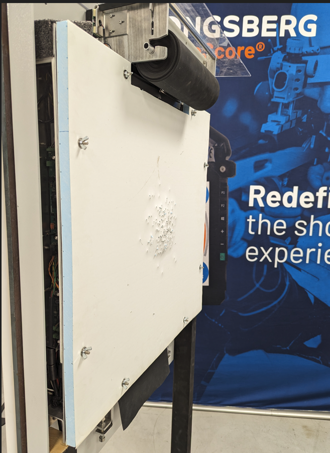 |
| If reinstalling a used temperature shield, take care to observe what side of the temperature shield is expanding most, and let that part be on the outside of the target. |  |
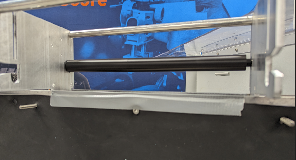
Installing or changing the rubber roll
The rubber roll sits on the top of the target construction, and together with the rubber roll brake create the appropriate tension on the rubber band that is pulled down in front of the target by the feeding mechanism in the bottom of the target.
| Install the rubber roll axle though the rubber roll. Lock the axle with one C clip on each side. | 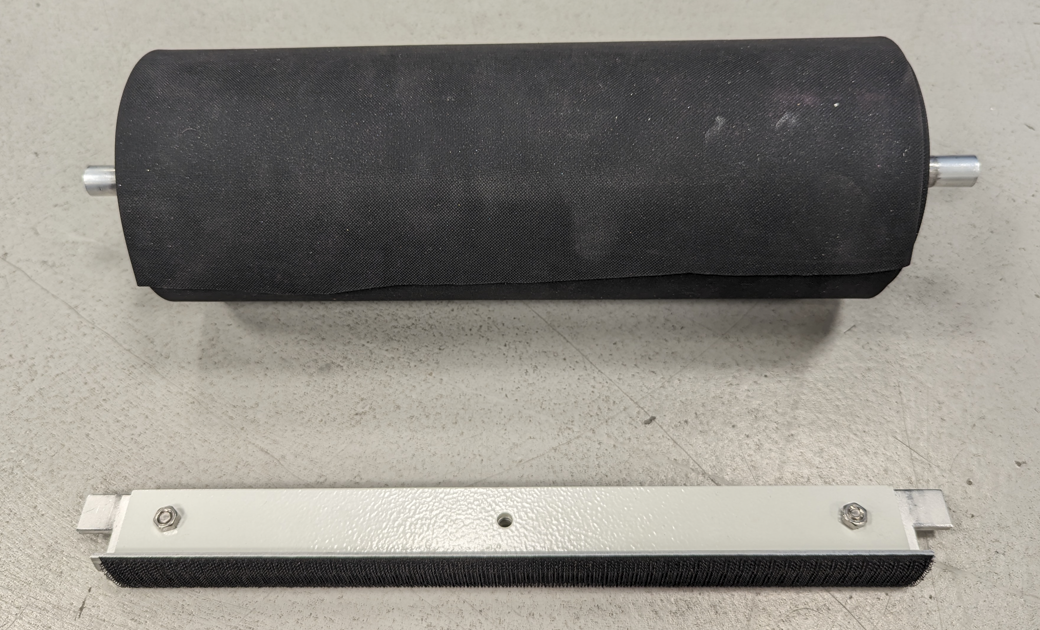 |
| Open the target, and from the rear, set the axle onto the holder brackets of the target, keep the C clips on the inside of the brackets on both sides. Note the position of the outgoing rubber, it will later be pulled off from the top of the roll towards the front. | 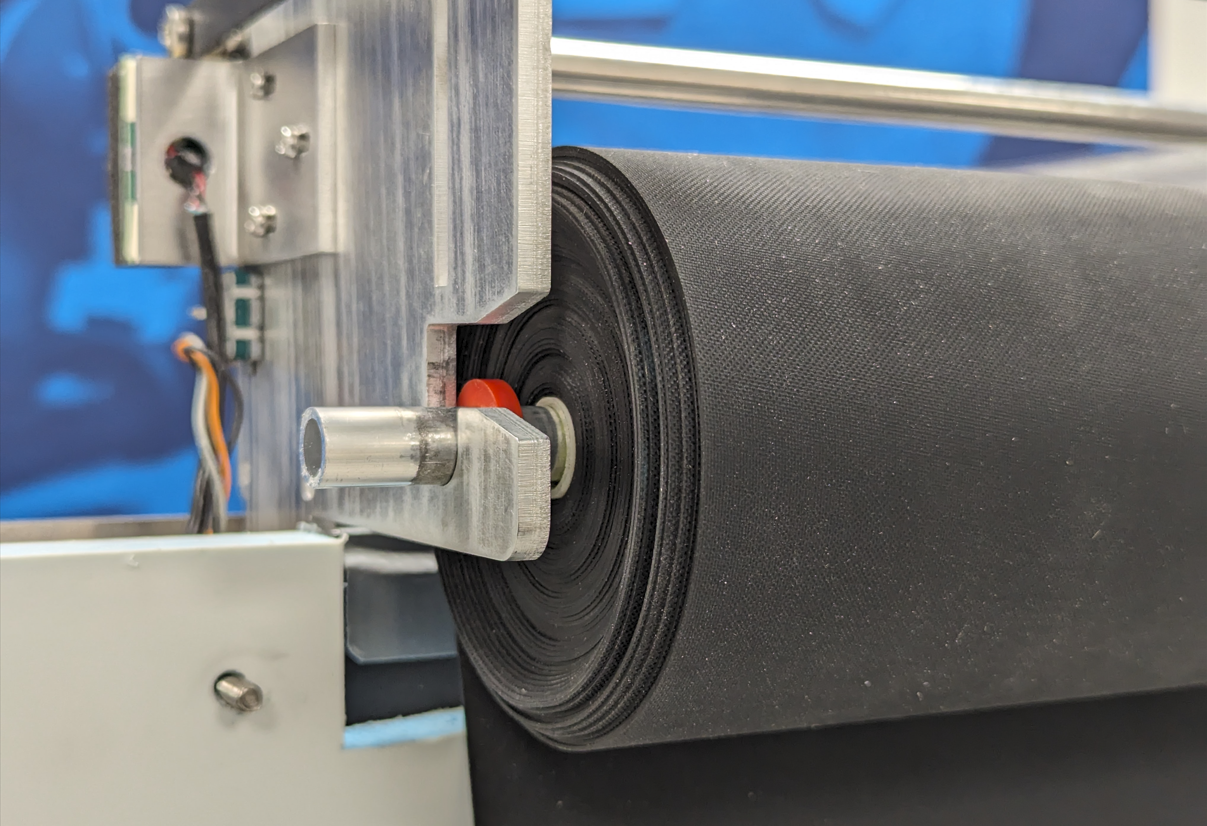 |
| Put the rubber roll brake in place. | 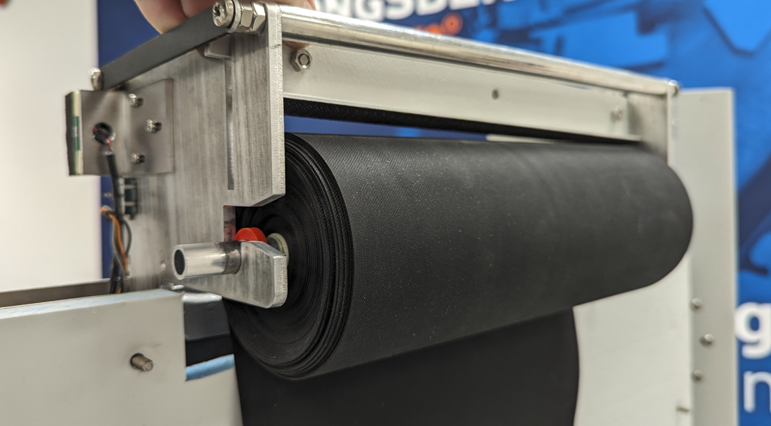 |
| Open the target even more, to access the target frame front. Pull the end of the rubber roll out | 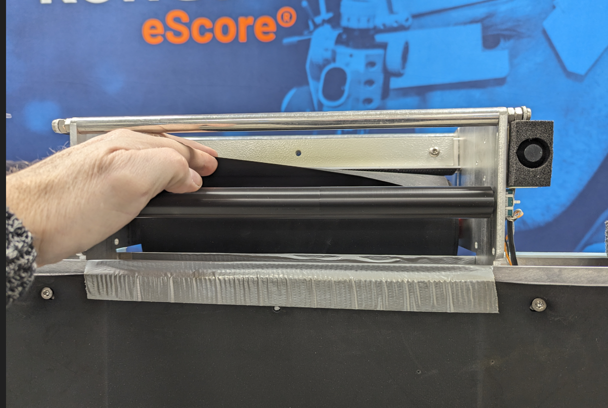 |
| and over the roller on top of the target. | 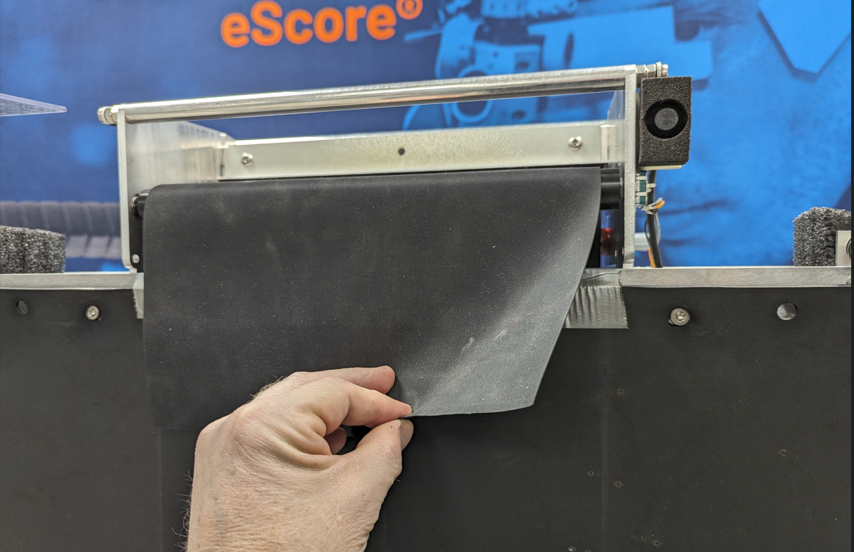 |
|
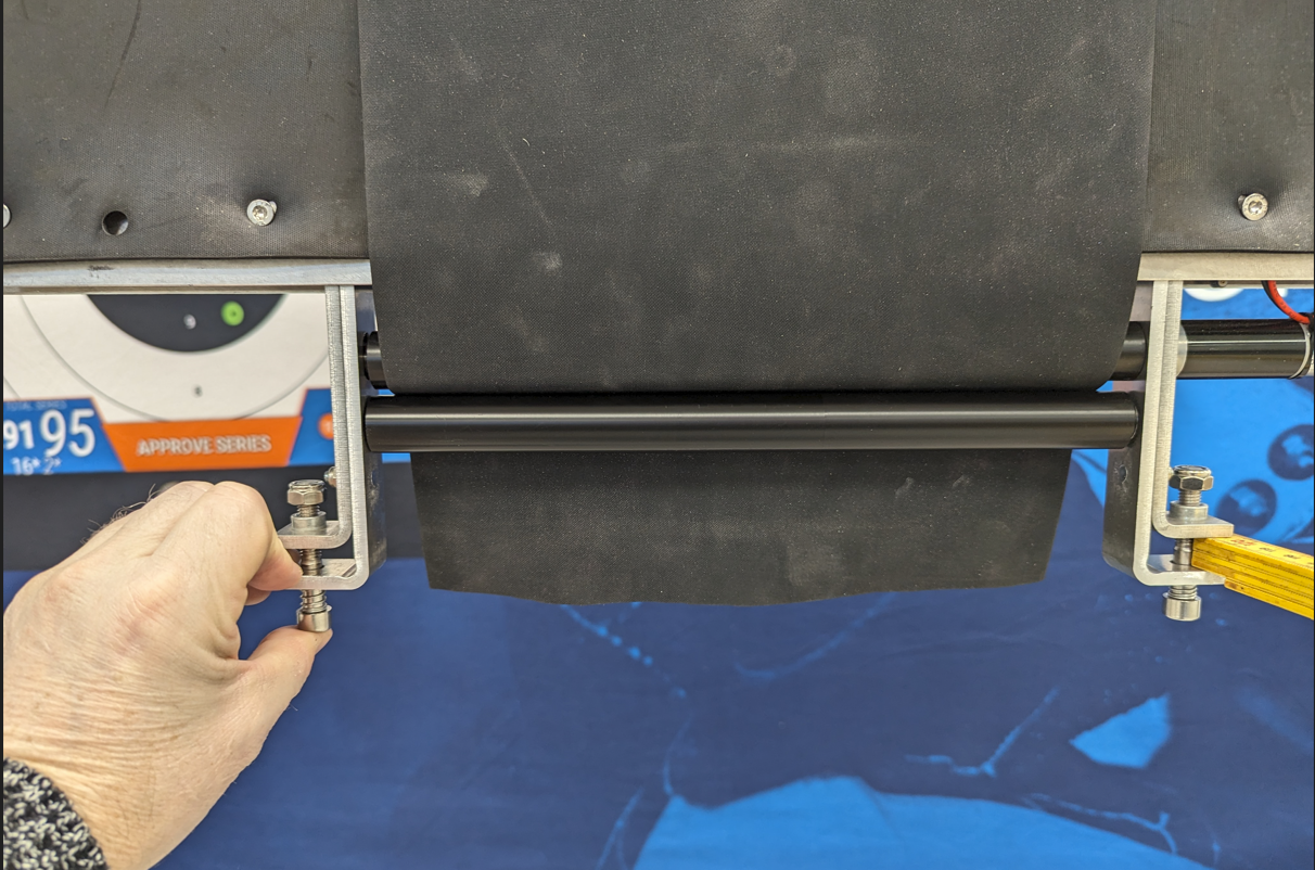
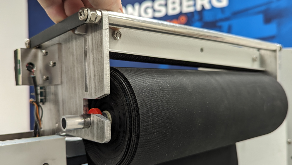
Pull the rubber band to the bottom of the target. By pushing the outer brackets (holding the top roller) an opening is created. This can also be done by pressing the Hex screws up like shown on the picture.
Thread the rubber through the opening, and take care to center the rubber in the opening. Release the forced opening of the rollers and let the springs keep the rollers pushed together.
Install the front template as described in chapter “Changing the front template”. |
 |
Changing the front template
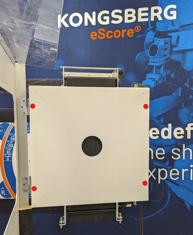
The front template/aiming mark is held to the target frame with 4 studs. The threads on these studs will ensure a precise location of the aiming mark on the target frame each time it is installed.
|
Open the target from the back and locate the front template over the target frame. Take care in positioning the studs on the target frame (indicated position by red marks on the picture) behind the corresponding holes in the front template. Push the template over the studs on all four locations.
The front template has velcro on one side. The velcro must face the target rubber. |
 |
| Close the target, make sure that both upper and lower magnet locks well to the armor. |  |
|
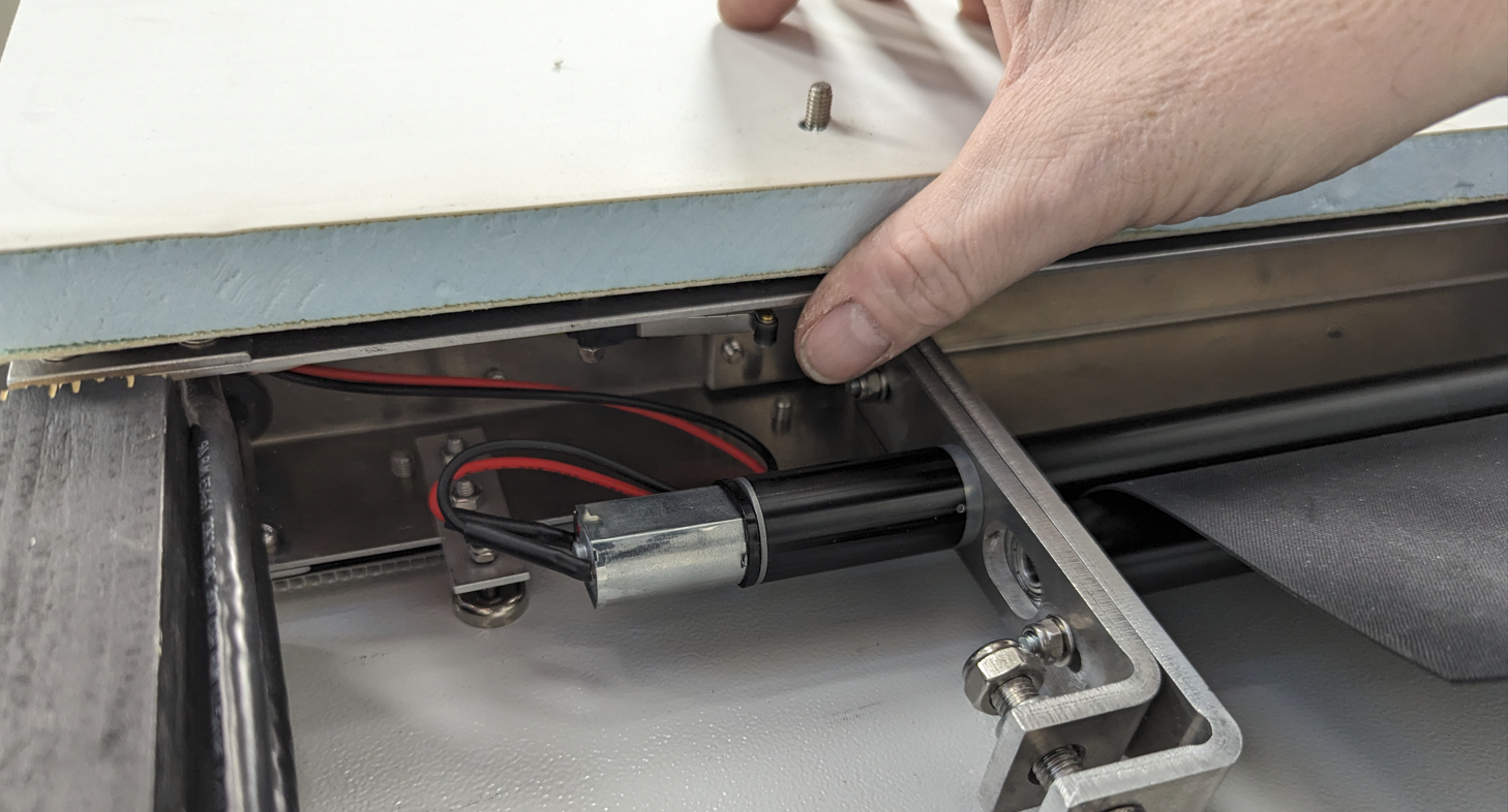
Run the feeding motor manually until the rubber roll on the top of the targets starts to unwind. The switch to manually run the feeding motor is located right above the motor, easiest reached from behind the target.
This must be done to tighten up the rubber strip, and to verify free movement of the rubber strip. |
 |
Inspection, adjustment and repair
Inspect and adjust the rubber feeding mechanism
|
The rubber feeding mechanism ensures that the rubber strip is moved downward from the roll at the interval and length decided by the target. This keeps the scoring rubber surface in the center of the target fresh and ensures the optimal accuracy.
The top roll of the feeding mechanism is driven by the motor and is mounted floating and it is pressed downwards towards the second roll by one spring on each side. This ensures that enough pressure is applied to avid slip between the driven roll and the rubber strip.
Check, maintain and possibly adjust as described below every time the rubber roll is changed, or every 6 months. | |
|
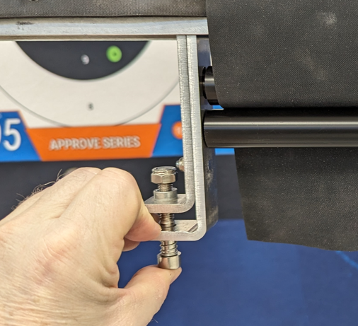
Check: Press the bottom screw upwards, and ensure the free movement of the movable bracket and the stationary one (holding the lower roll). Check both sides.
Adjust: The pre-tension of the springs can be adjusted by turning the screw. Make sure the tension is approx equal on both sides. The springs should be adjusted in case slip of the rubber strip feeding is observed. The springs should not be so tight that it will bend or deform the rollers.
|
 |
|
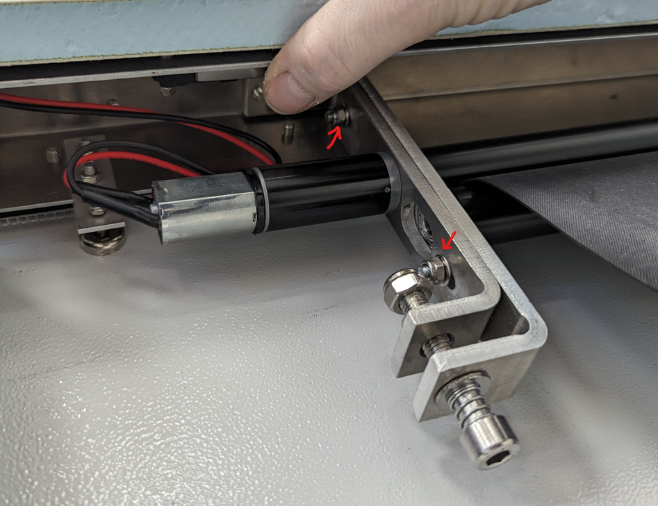
Maintain: Lubricate the surface between the moving and stationary bracket on both sides using thin oil. Dry off any excess oil.
Adjust: un-tighten or tighten the nuts (red arrow) if needed. The brackets should move easily but not be too loose.
|
 |
Inspecting the rubber feeding sensor
|
The rubber feeding sensor will set an alarm in the eScore system if the rubber is not moving as expected. If the systems is throwing errors even if the rubber is feeding correctly, inspect the rubber feeding sensor roller.
The construction is based on a free rotating roll at the top of the target having a rotational sensor attached.
Check as described below every time the rubber roll is changed, or every 6 months | |
| Check: rotate the roller by hand, and feel that the roller turns easily. Some limited friction is created by the rotational sensor, but this should be constant through the full rotation of the roller. | 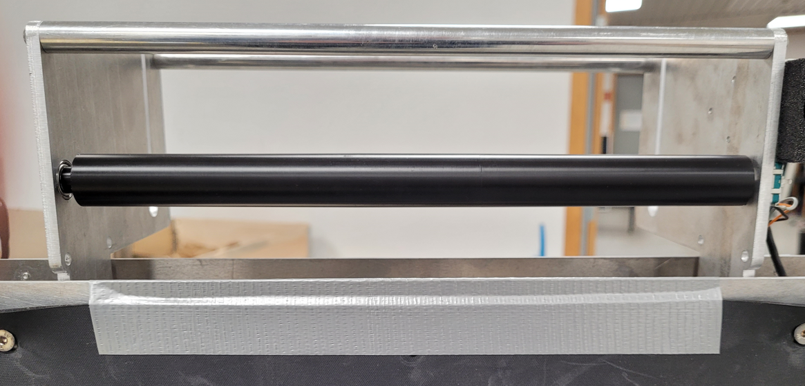 |
|
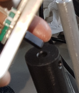
Replace: If the friction is not as expected, replace the rotation sensor (attached to the roller with an hex set screw), or replace the ball bearing if that is the cause.
Note: if removing the rotational sensor, make sure the set screws meet the flat surface on the axle, and do not over tighten since the sensor axle is plastic.
|
 |
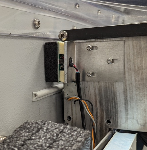
Inspect and adjust the miss sensor
|
The miss sensor will set an alarm or discriminate signals in the eScore system if vibrations from a hit is detected in the base armor by the sensor.
Check and possibly adjust as described below every time the rubber roll is changed, or every 6 months | |
|
Check that the black foam gasket surrounding the sensor is in place. Replace if needed.
Check that the distance between the sensor and the surface on the inside of the base armor when the target is closed is approx 1mm.
Adjust the distance if needed by loosening the three M3 screws holding the sensor bracket, reposition and re-tighten.
Check that the white rubber gasket “P-gasket” is in place below the sensor. Replace if needed.
|
 |
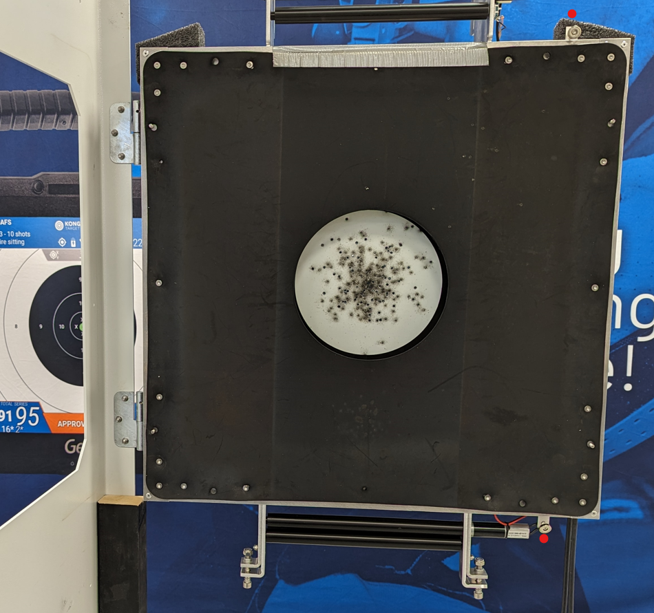
Adjusting the magnet locks
| The magnet locks keeps the target frame closed to the rear of the base armor during use. It is two magnets, one at the top and one at the bottom of the target. These are adjusted the same way, but the foam rain cover must be removed to adjust the top one. | |
|
The magnets location is indicated by the red dots.
Check that the magnets are fully locking to the base armor when closed. The target must be set up as when shooting, with main rubber sheet, rubber roll and front template in place.
Check that it is a free play of approx 5 mm by pressing the target frame towards the armor both at the top and the bottom of the target. |
 |
|
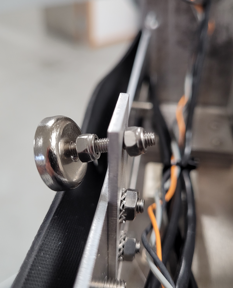
Adjust the magnet location by shortening or lengthening the screw holding the magnet by turning the nut furthest away from the magnet.
If adjustments are made, the miss sensor location must be checked and possibly adjusted. |
 |
Inspecting the rubber roll brake
| The rubber roll brake control the tension of the rubber strip between the roll and the feeding mechanism. | |
| Check that the Velcro tape is complete and well attached to the rubber roll brake. Replace the tape if worn or loose. | 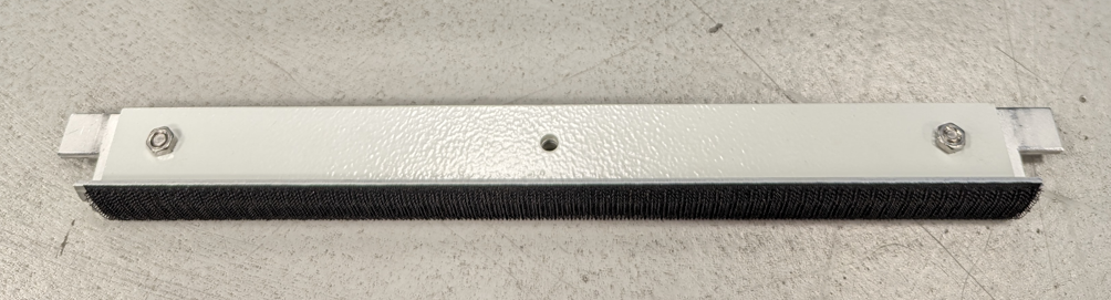 |
|
Check that the roll brake can slide freely in the slots on the roll holder brackets. If stuck, check the surfaces of the end tabs of the brake. Straighten, deburr the end tabs or replace the brake if needed.
Check that the brake works evenly when running the feeding motor manually. Se “Changing rubber roll”. |
 |
Checking the rain and dust covers
| Rain and dust covers. Check and replace if needed. | |||||
| Top rain cover. Attached to the base armor with screws from the back. Replace if cracked or broken. Attach “P-gasket” to the cover before attaching to the armor. | 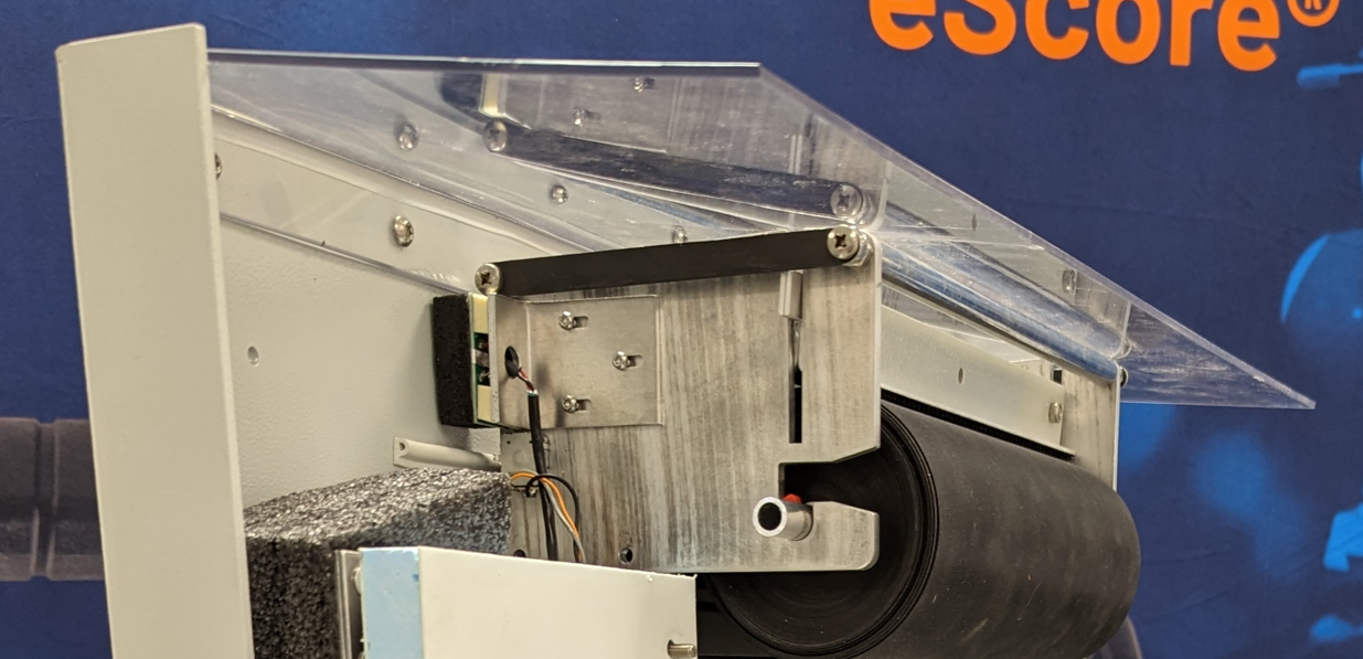 |
||||
| Corner rain cover. Replace if damaged or missing. Flexible, squeeze together and set in position. | 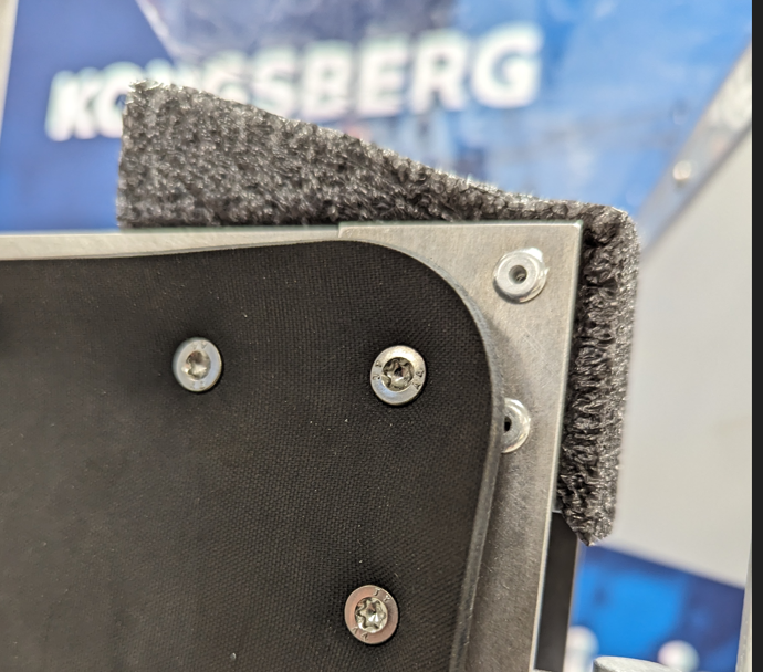 |
||||
|
Transparent side cover. Check for cracks and replace if needed. Held in place with 8 screws, and is positioned under a gasket.
Removal of the transparent side cover.
Installation of the transparent side cover
Replace gasket if damaged. |
 |
||||

Possible adaptions
Shorter range adaptions
Though this target is mainly intended for 25/50 m/yds use, it might be fitted with smaller front templates to be used at shorter distances. Latest revision of the ISSF 25/50m precision pistol front template (KTS part no 13020439) have aiming marks to accurately fit paper templates (mask targets) typically used for shorter ranges. These paper targets are simply added (taped) to the ISSF 25/50m precision pistol front template.
 Before adaption |
 After adaption |
Following short range templates exists:
| Target definition (spot size) |
KTS part no: (Mask target) |
| NSF 15m rifle (Ø34.8mm) | 97020684 |
| DFS 15m rifle (Ø38mm) | 97020677 |
| DDS/DGI 15m rifle (Ø42.8mm) | 97020670 |
| DDS/DGI 15m pistol (Ø100mm) NSF 15m Colt (Ø100mm) |
97020683 |
Replacement of electronic parts and cables
Target input/output cables
| The target input/output cable assemblies are available as spare parts. Each target has one male (input) and one female (output) cable, either M23 (metal) or Amphenol (Plastic) connectors. To replace a cable, follow the following procedure below. | |||
|
Removal of the transparent side cover.
| |||
| Remove the M3 nut holding the two protective earth cables to the chassis of the target frame. | 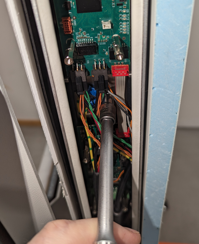 |
||
| Remove the connectors from the target electronic by pressing the locking lug in, and pull the connector downwards. | 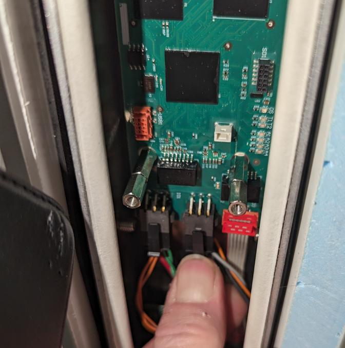 |
||
| Connector off. Remove both even if just one input/output cable will be changed. | 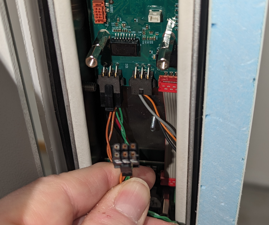 |
||
| Cut the two cable ties holding the two cables together. | 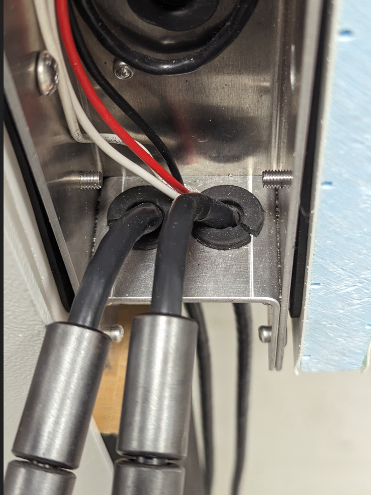 |
||
| Remove the rubber grommet for the cable that should be changed. | 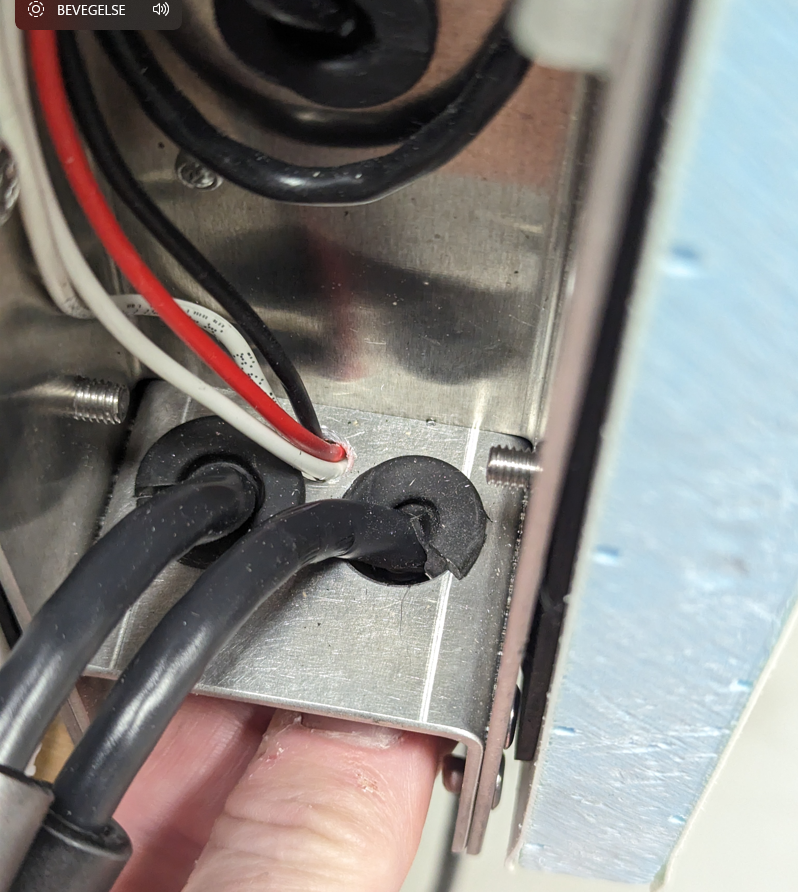 |
||
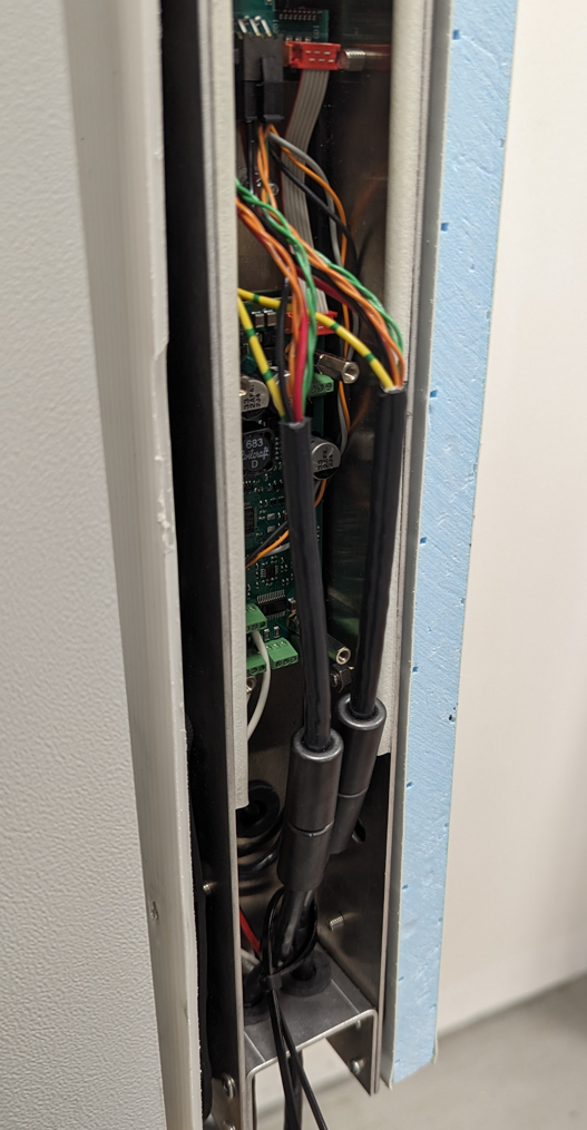
| With the grommet removed, the ferrit cores can be threaded through the openings in the target frame. | 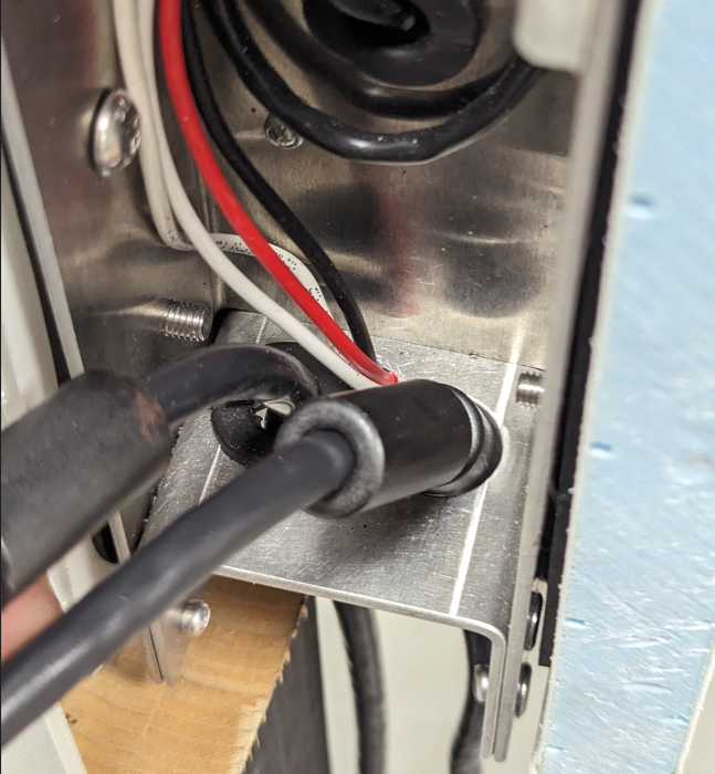 |
||
| The cable assembly removed. Ready for new assembly. | 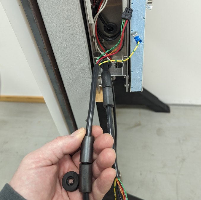 |
||
| Installation is basically the reverse of the removal. Take care in positioning the rubber grommets with the cut out pointing away from the other grommet. | 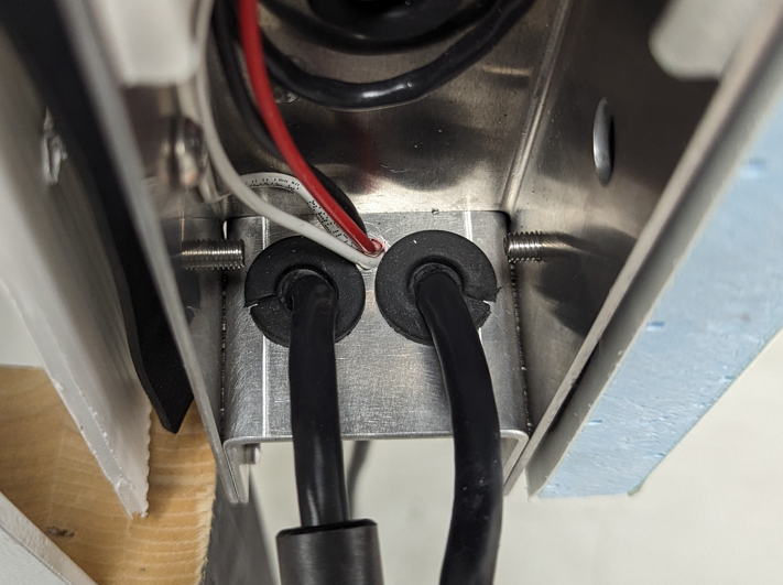 |
||
| Attach the protective earth, the two cables should point right from the stud. | 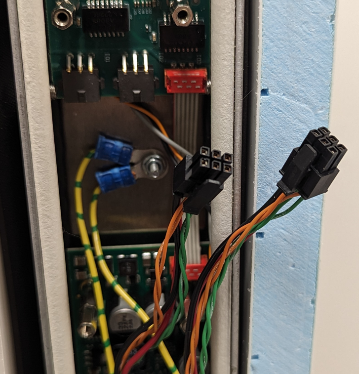 |
||
|
Connect the box connectors to the target electronic circuit board. Push in until a weak “click” is heard. The two circuit board connectors are identical, either can be used for both cables.
Use two cable ties around the output/input cable to create a strain relief. Tighten the cable ties, but take care keeping a slack on the cables above the cable ties. |
 |
||
Installation of the transparent side cover
| |||
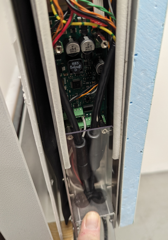
Circuit boards
| Changing the circuit boards. Both circuit boards are located on the side of the target frame, and is attached to the frame in the same way. All non terminated wires are connected to the circuit boards using screw terminals. Note: Take care in not over tightening the terminal blocks. Always, after re-connecting, check if the wire sits well in the terminal block and that no strands are outside the terminal block. | |||
Removal of the transparent side cover.
| |||
|
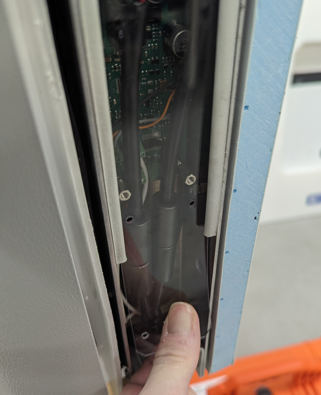
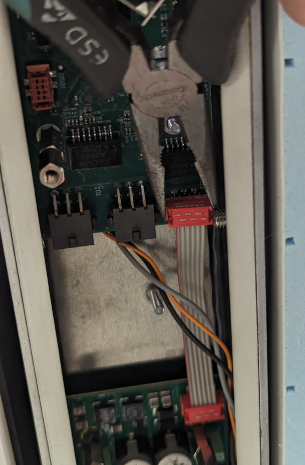
Remove the connecting cable between the two circuit boards carefully. Top circuit board: ITE. Bottom circuit board: Auxiliary board.
Remove in/out cables as described in other chapter |
 |
||
| Remove the four extension nuts holding the circuit board that is to be changed. | 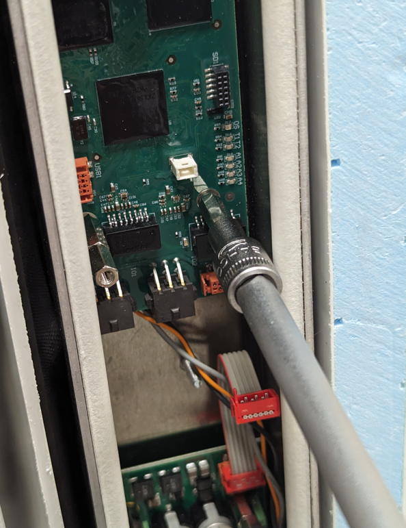 |
||
| The studs are attached to the target frame, and it is four 5mm long spacers on these studs behind the circuit board. | 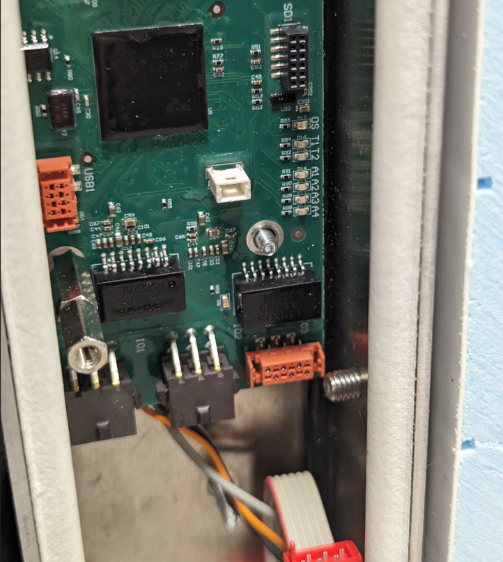 |
||
|
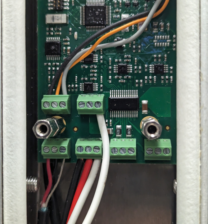
Auxiliary board: Note the wire locations.
Black/orange/white: Rotation sensor.
White + white: Switch for forced motor feeding.
Red/black/silver: Miss sensor.
Black/red: Feeding motor. |
 |
||
|
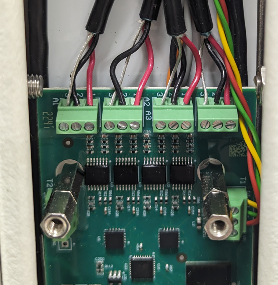
Target Electronic (ITE): Four acoustic sensor input connectors, A1, A2, A3, A4 as seen to the right.
A1: Top right Acoustic sensor A2: Bottom right Acoustic sensor A3: Bottom left Acoustic sensor A4: Top left Acoustic sensor
Yellow/green/red: Temperature sensor. |
 |
||
Installation of the transparent side cover
| |||
Target sensors, rotation sensors and miss sensor
| Changing acoustic sensors, miss sensor, rotation sensor or feeding motor should be done only after determining that the sensor is actually the issue. The eHub status will be of great assistance in this case. | |||
Removal of the transparent side cover.
| |||
|
The acoustic and temperature sensors are connected to the top circuit board, the ITE (Internal Target Electronic board).
A1: Top right Acoustic sensor A2: Bottom right Acoustic sensor A3: Bottom left Acoustic sensor A4: Top left Acoustic sensor
Yellow/green/red: Temperature sensor.
After changing any sensor or motor: Route the cable, cut the cable to appropriate length and connect it to the corresponding terminal block. Note: Do not over tighten the terminal block screw, check that no strands is poking out, and pull carefully in the wire to make sure it is well connected.
The acoustic sensors are attached to the target frame with double sided tape. Make sure to remove any glue or rest of tape from the old sensor, clean the surface well with de-naturized alcohol and apply the sensor (with tape already in place) in the same position as the old sensor.
To change the temperature sensor, the circuit board must be lifted out slightly. Other cables can be kept in place. Temperature sensor is located in the top right corner of the target. Cut the replacement sensor wires to appropriate length.
|
|
||
|
Auxiliary board: Note the wire locations.
Black/orange/white: Rotation sensor.
White + white: Switch for forced motor feeding.
Red/black/silver: Miss sensor.
Black/red: Feeding motor.
After changing any sensor or motor: Route the cable, cut the cable to appropriate length and connect it to the corresponding terminal block. Note: Do not over tighten the terminal block screw, check that no strands is poking out, and pull carefully in the wire to make sure it is well connected. |
|
||
Installation of the transparent side cover
| |||
Spare parts and consumables
Consumables
| Front template, ISSF 50m Rifle | 13020432 |  |
| Front template, ISSF 25/50m precision pistol | 13020439 |  |
| Front template, ISSF 25m Rapid Fire Pistol H3D/H4D | - | |
| Rubber roll 260mm. | 97020790 | 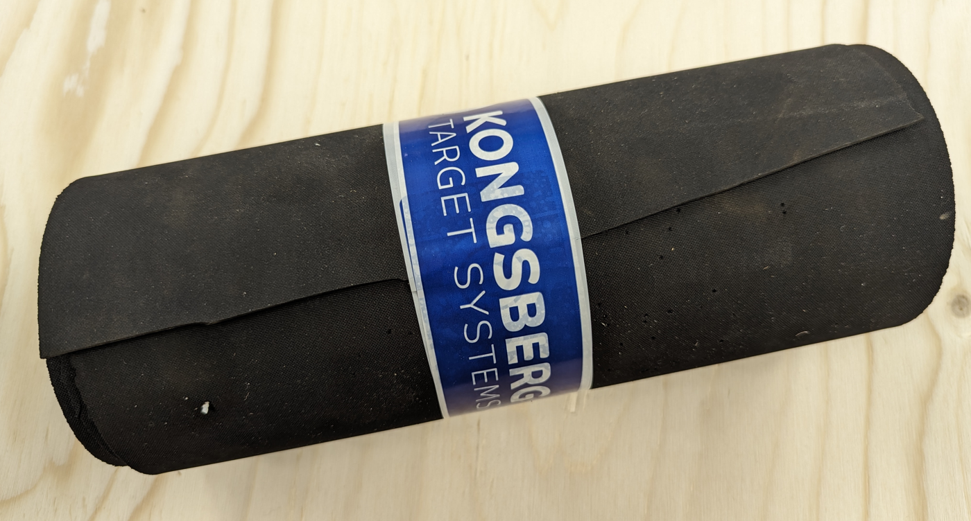 |
| Main rubber skin front/rear - Target H4D | 13020329 | 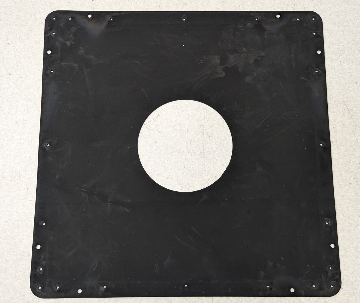 |
| Rear temperature shield - Target H4D | 13020427 | 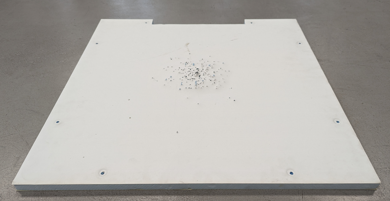 |
 |
||
| Color code for the steel base armor: | RAL7035 Bright Gray |
Spare parts
| Axle, rubber roll, H3D/H4D | 97020413 | 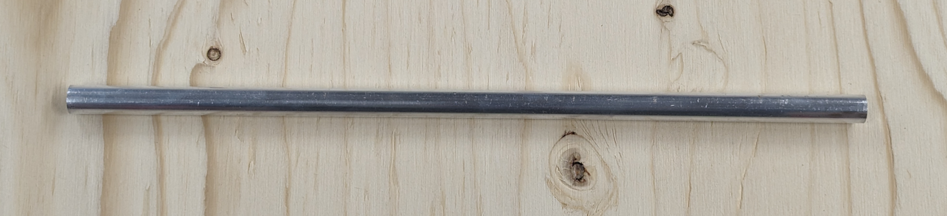 |
| C-clips for rubber roll axle | 1507001 | 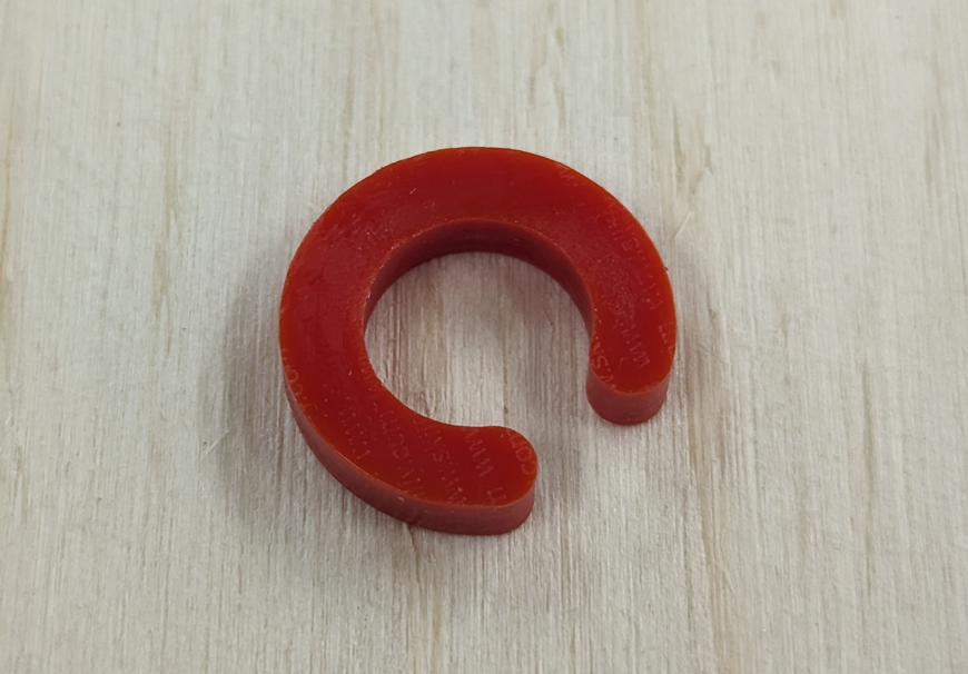 |
| Top cover, transparent - Target H4D | 13020330 | |
| Corner rain shield - Target H4D | 13020395 | |
| Cover, transparent, target electronics - Target H4D | 13020358 | |
| Miss sensor foam gasket - Target H4D | 13020380 | 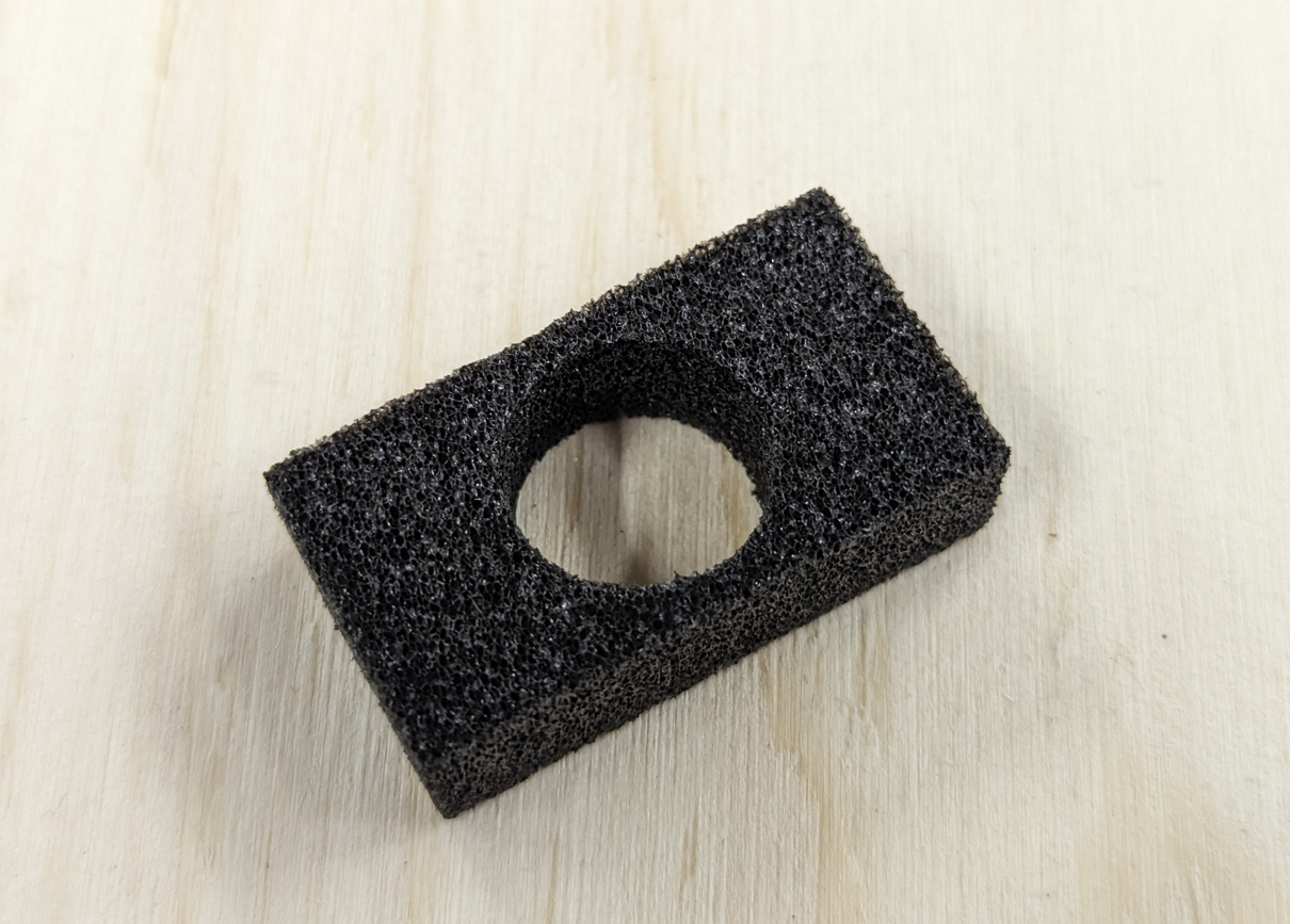 |
| P-gasket, X cm length | 3202009 | 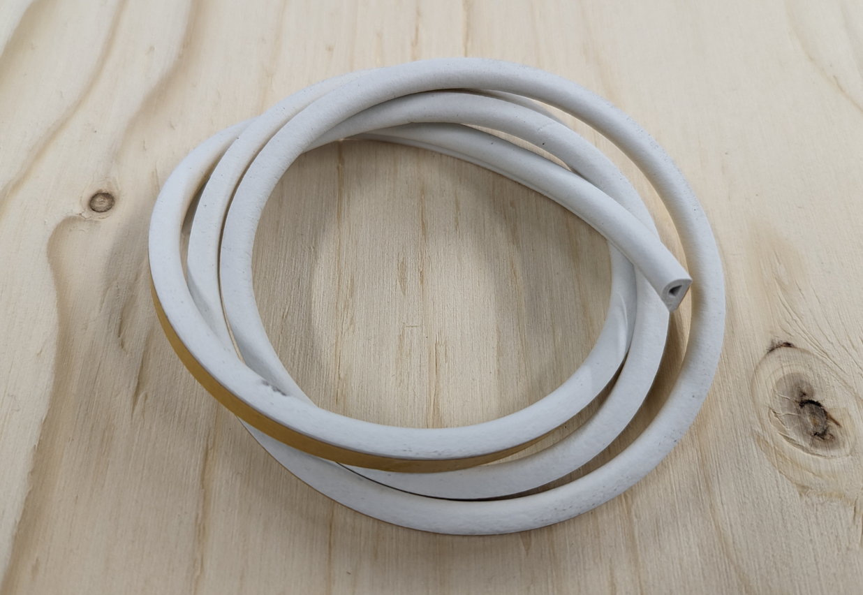 |
| Velcro tape for rubber roll brake, X cm length | 3203001 | |
| Rubber grommet | 1707012 | 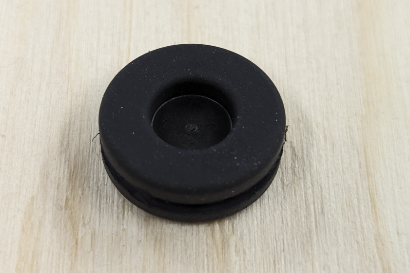 |
| Input/Output cable M23 Male | 13020190-85cm | 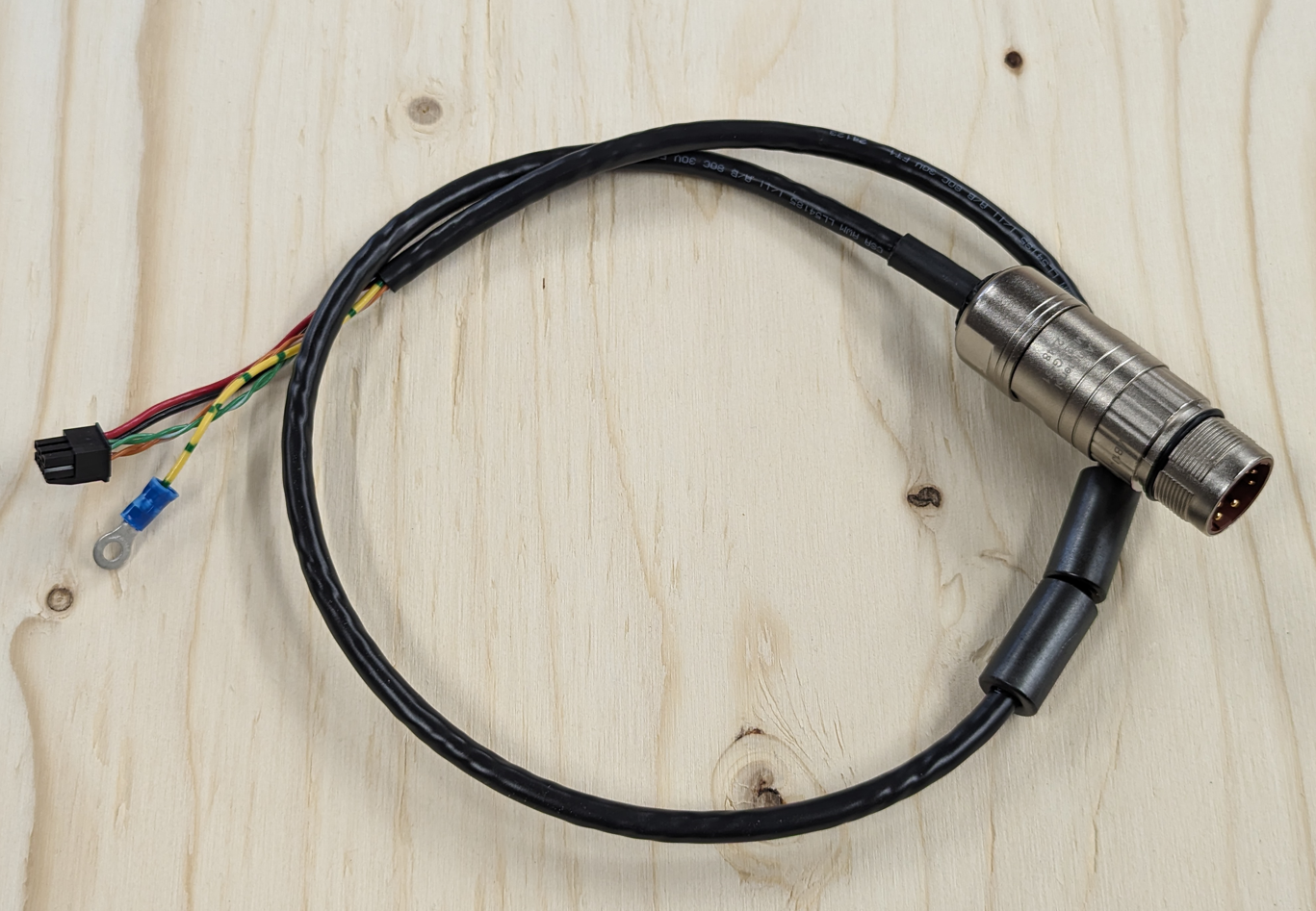 |
| Input/Output cables M23 Female | 13020191-85cm | 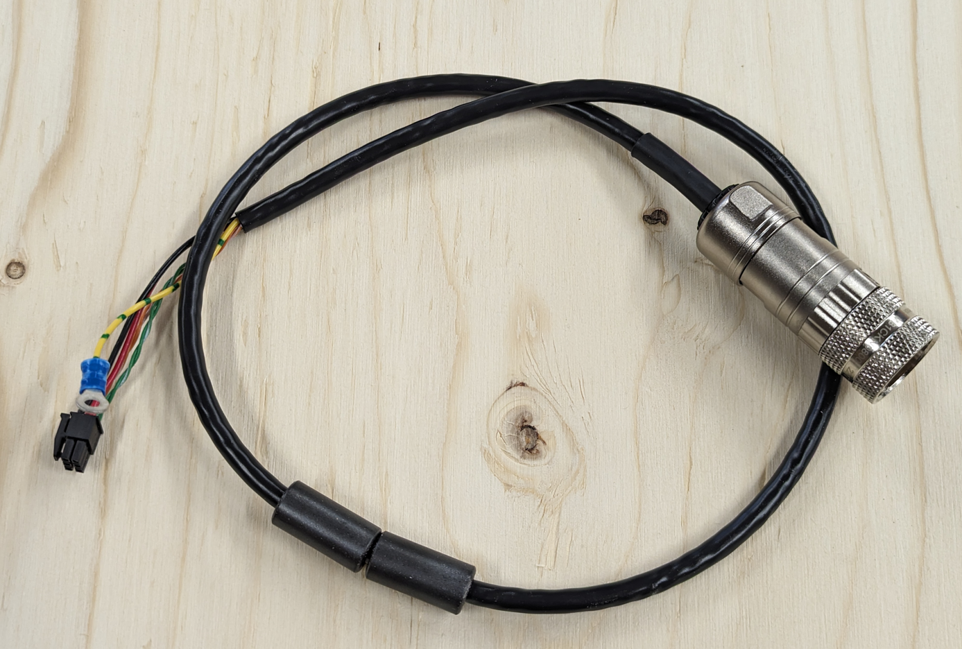 |
| Input/Output cables Amphenol Male | 13020209-85cm | 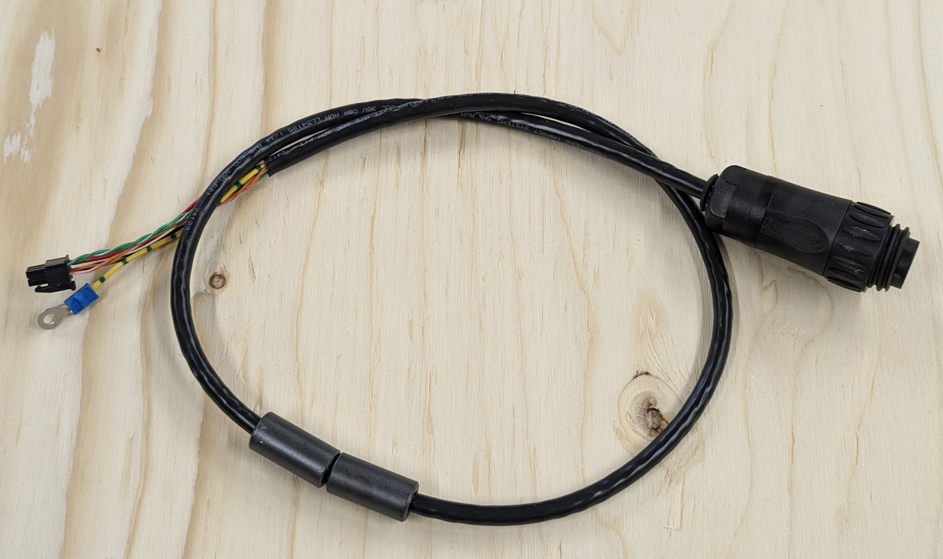 |
| Input/Output cables Amphenol Female | 13020210-85cm | 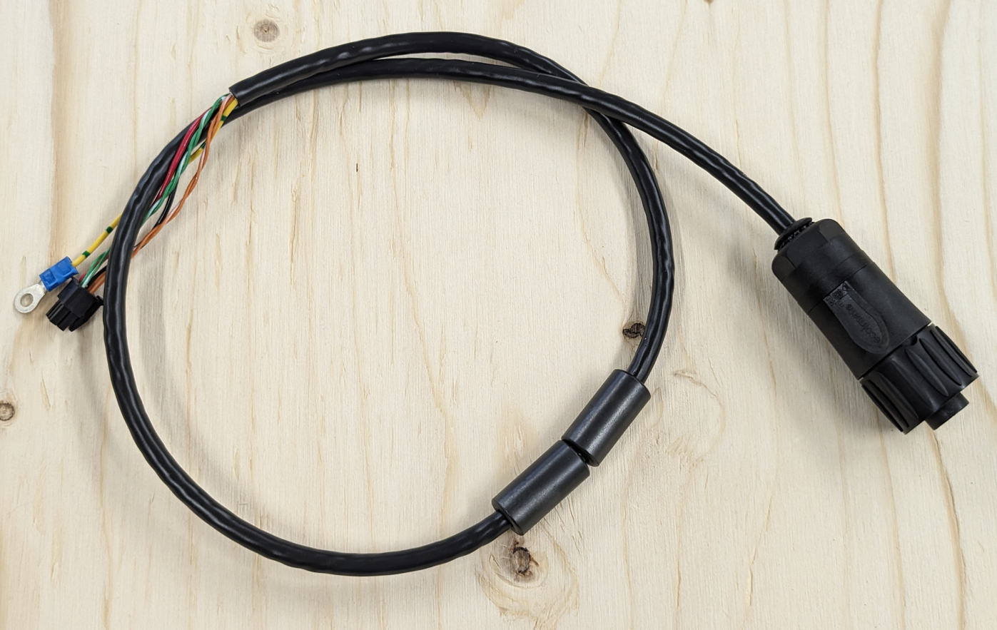 |
| Acoustic sensor | 97 02 0378 - 240 cm | 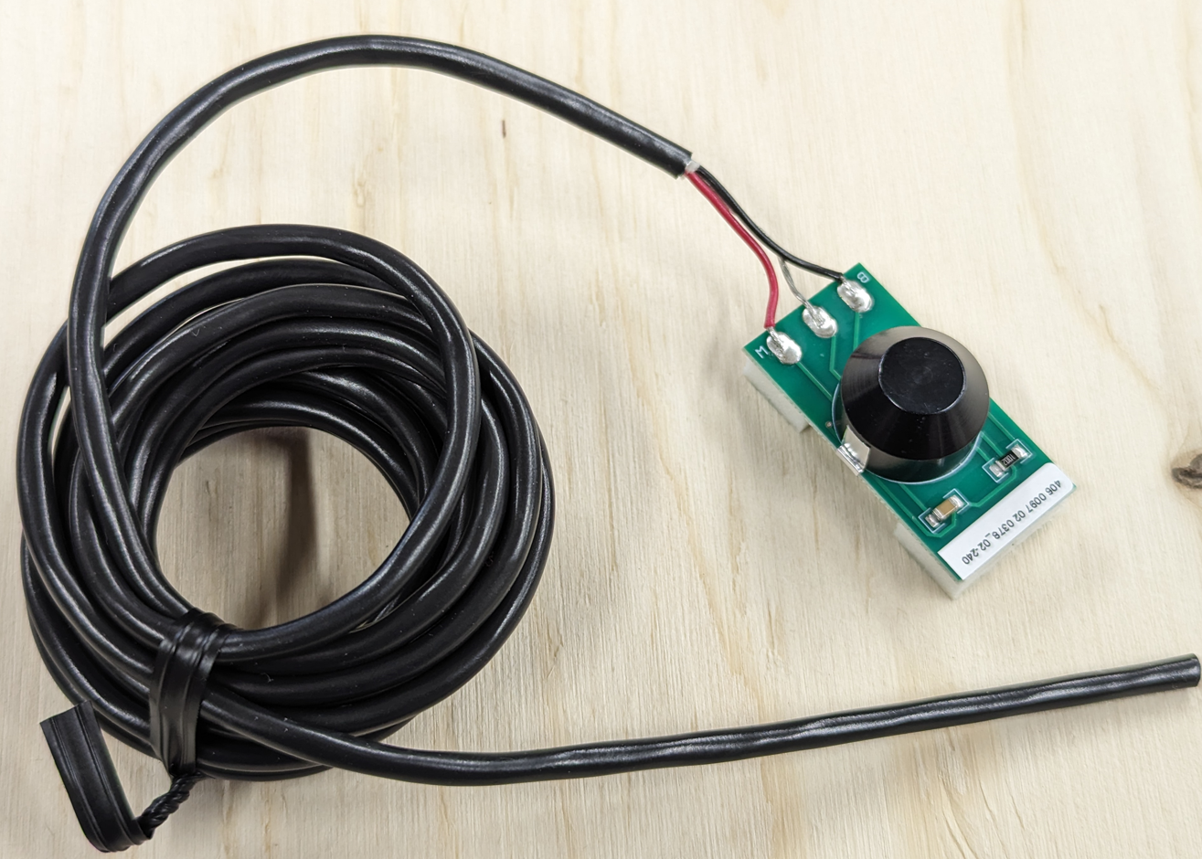 |
| Miss sensor | 97 02 0304 - 135cm | 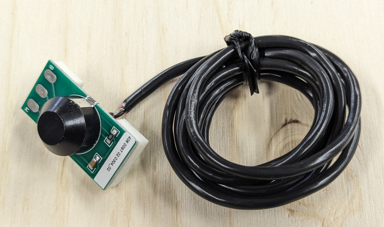 |
| Rotation sensor (excl wires) | 2302002 | 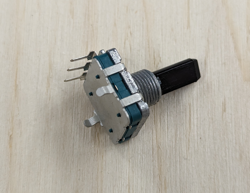 |
| Temperature sensor | 13 02 0842 | 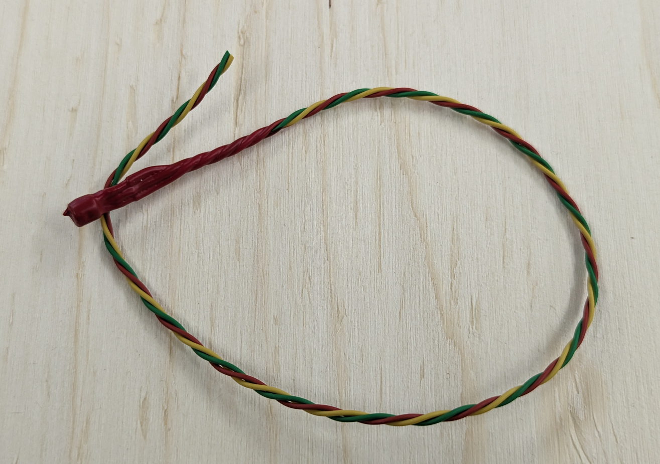 |
| Circuit board eScore Target Electronic (ITE) H4D | 13280000 - H4D | 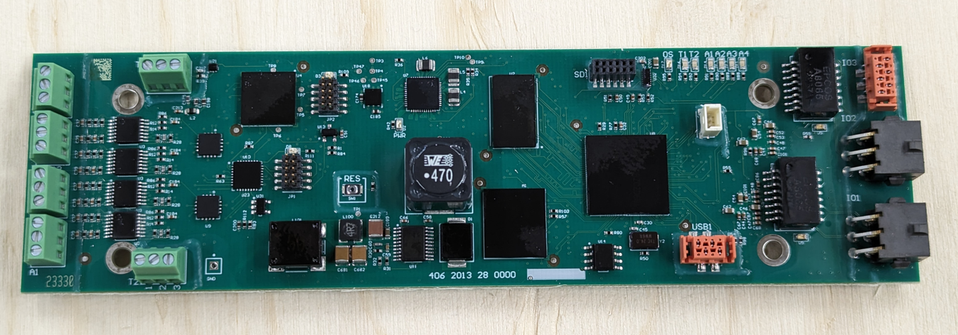 |
| Circuit board Auxillary eTK1 H4D | 13280002 - H4D | 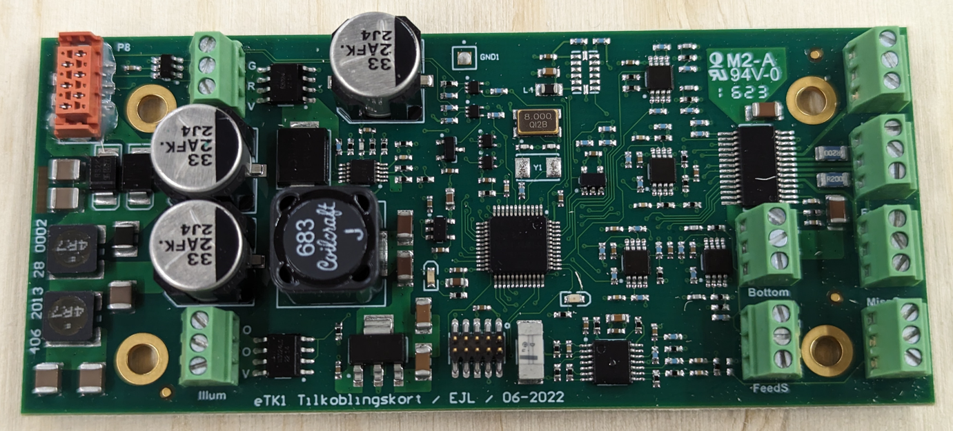 |
| Connection cable ITE - eTK1 H4D | 17 04 026 | 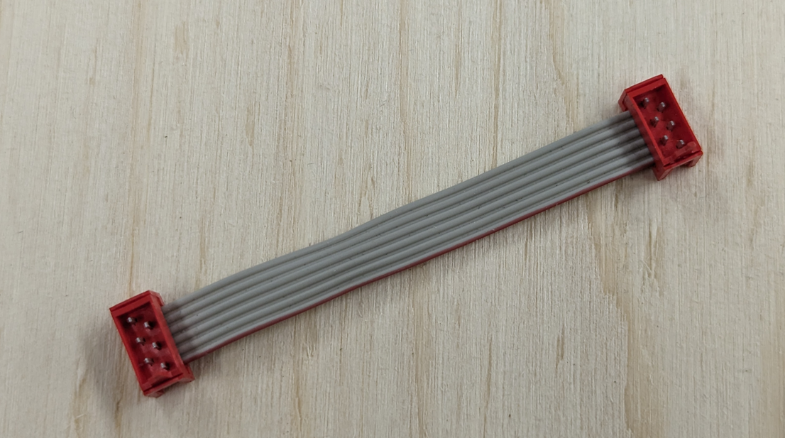 |