
Scope of this article
This article explains how to install Kongsberg Target Systems' eScore electronic scoring system at indoor shooting ranges. We beleive we have made the most easy to use, and easy to install target system of them all, but anyway…
Installing the power supply cabinet
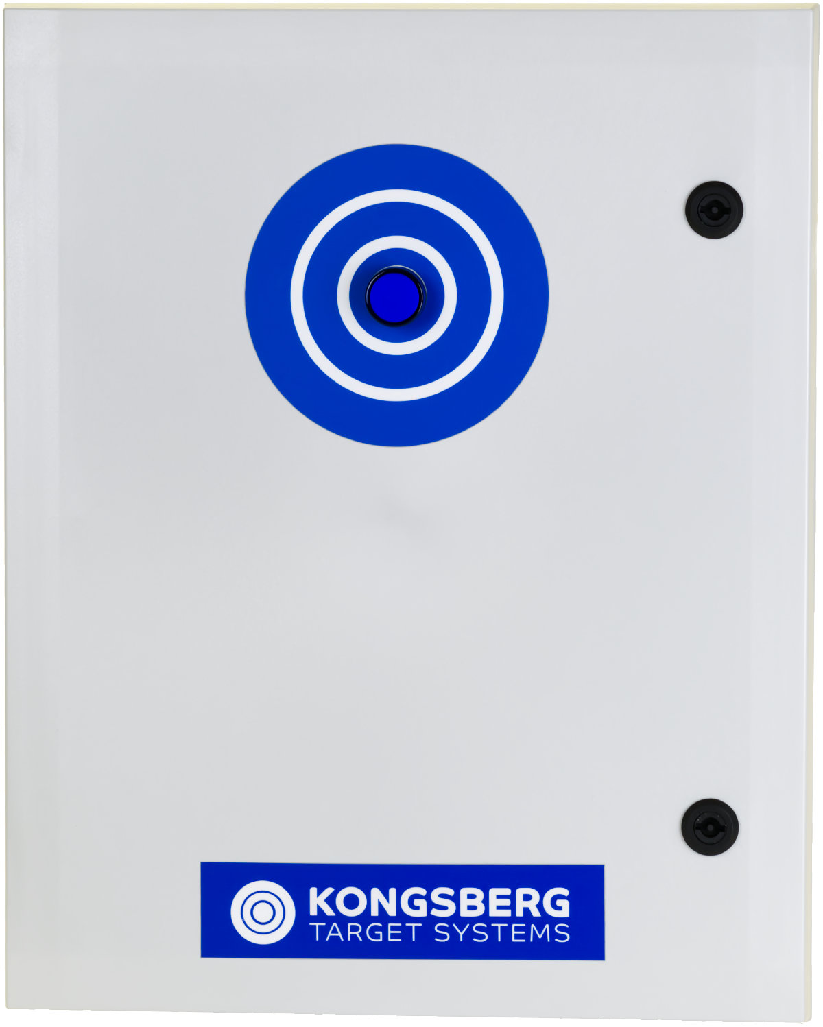
The supplied power supply cabinet (KTS part no 13360010 or 13360012) should be installed at one end of the target line..
Consider protecting the cabinet from stray bullets. A 63mm thick sheet of plywood, or a 5mm thick steel sheet will stop a .22LR bullet. National regulations may give guidance what's required/allowed at shooting ranges in each nation.
Warning!
Always consider the danger of causing ricoschets when installing electronic scoring targets, and do necessary precations to prevent so.
The cabinet may be attached to a wall. Screws, an extra long drill bit, and drill guide (for concrete wall) is supplied inside the cabinet. These ithems should be removed from cabinet before it is powered. Also, spare fuses are supplied. A key to open the cabinet is attached by a wire to the bottom of the cabinet.
Note!
Always disconnect mains power when working with the cabinet.
Assembling and installing the targets
Targets are assembled and installed at the shooting range as described in the OpticScore target user manual
System assembly is described below.
Installing power supply cabinet at one end of the target line
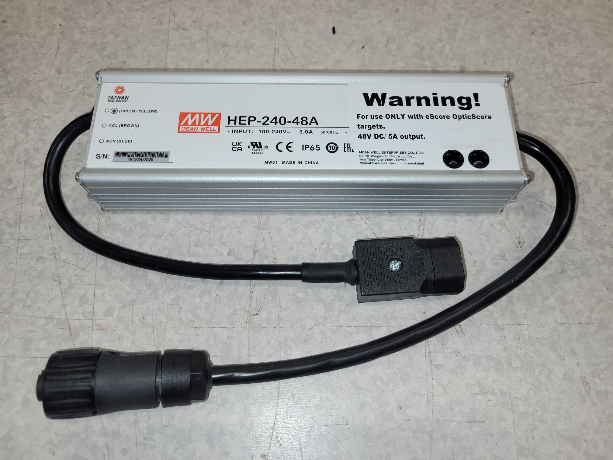
First or last target in the target line is initially connected to the power supply cabinet. However a 48V power supply (KTS part no: 13100014) need to be inserted between the cabinet and the target. When doing so, a supplied power injector cable (KTS part no: 13100002 or 13100004) will be utilized for this purpose, as shown at the sketch below.
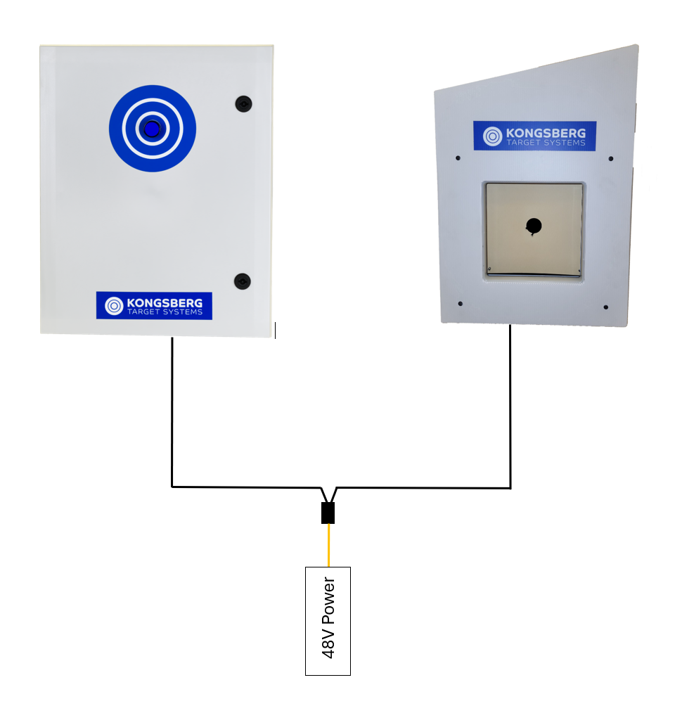
Orange cable end of the power injector cable is allways connected to the power supply.
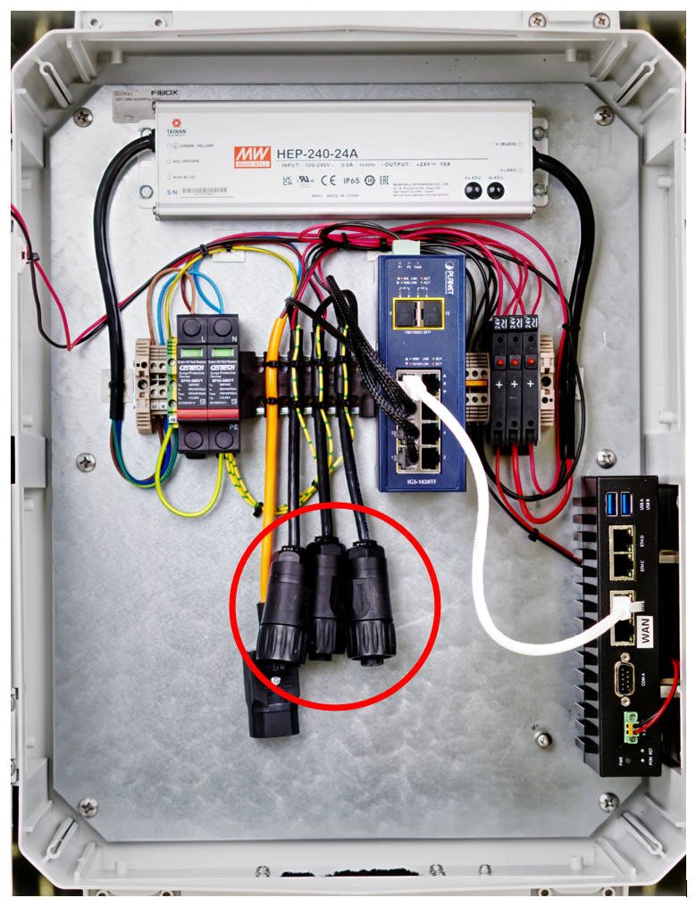
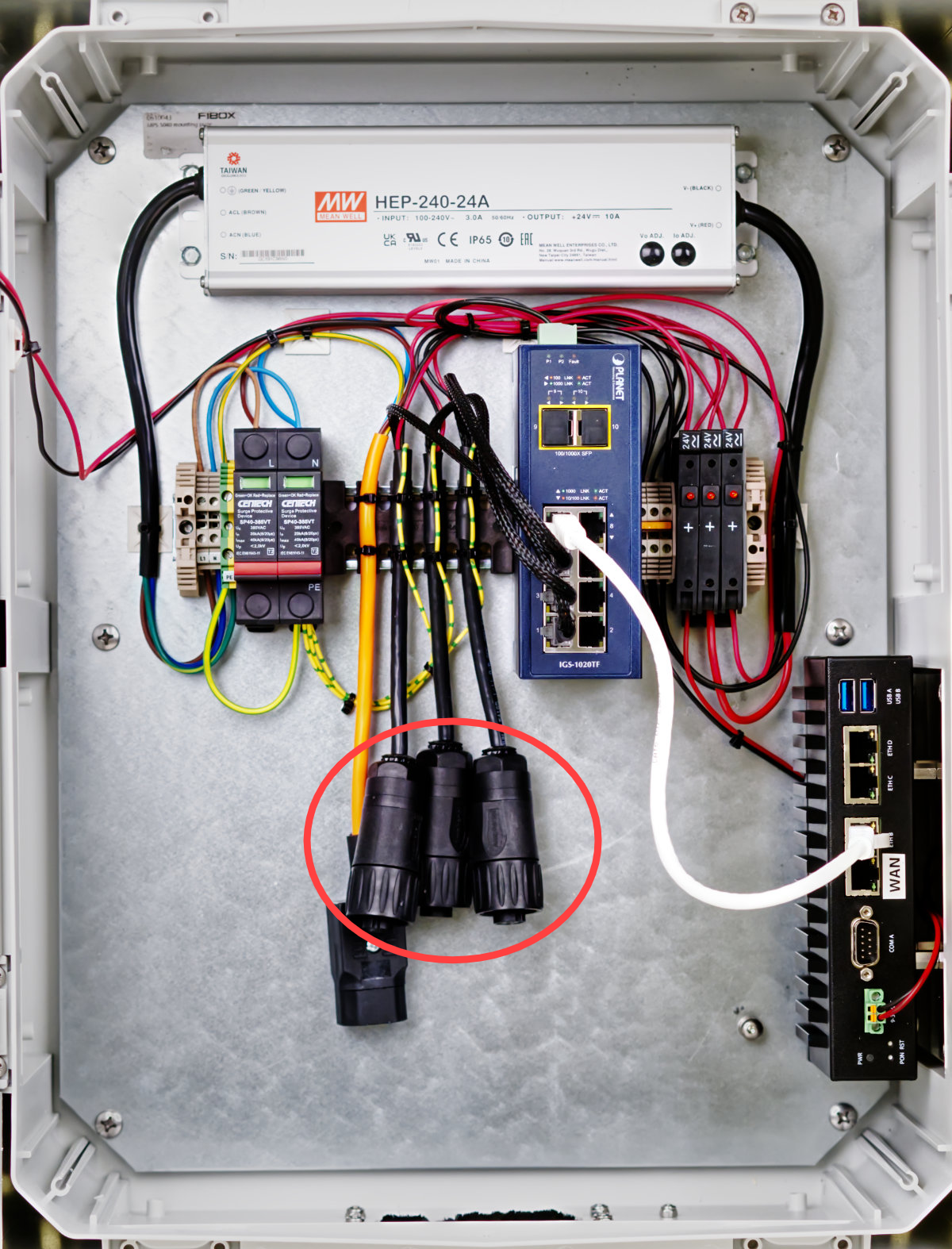
Cable(s) can be fit through the cable fitting at the bottom of the power supply cabinet. Power supply cabinet need to be opened to connect cables. Power injector cable is connected to one of the three output connectors.
Interconnecting targets
Targets are in general interconnected with target cables (see limitations below). By doing so, all targets will appear as a unified system.
 |
 |
Target cables may be supplied with different lengths. Please investigate what lengths are supplied to decide best fit and limitations to your range.
Note!
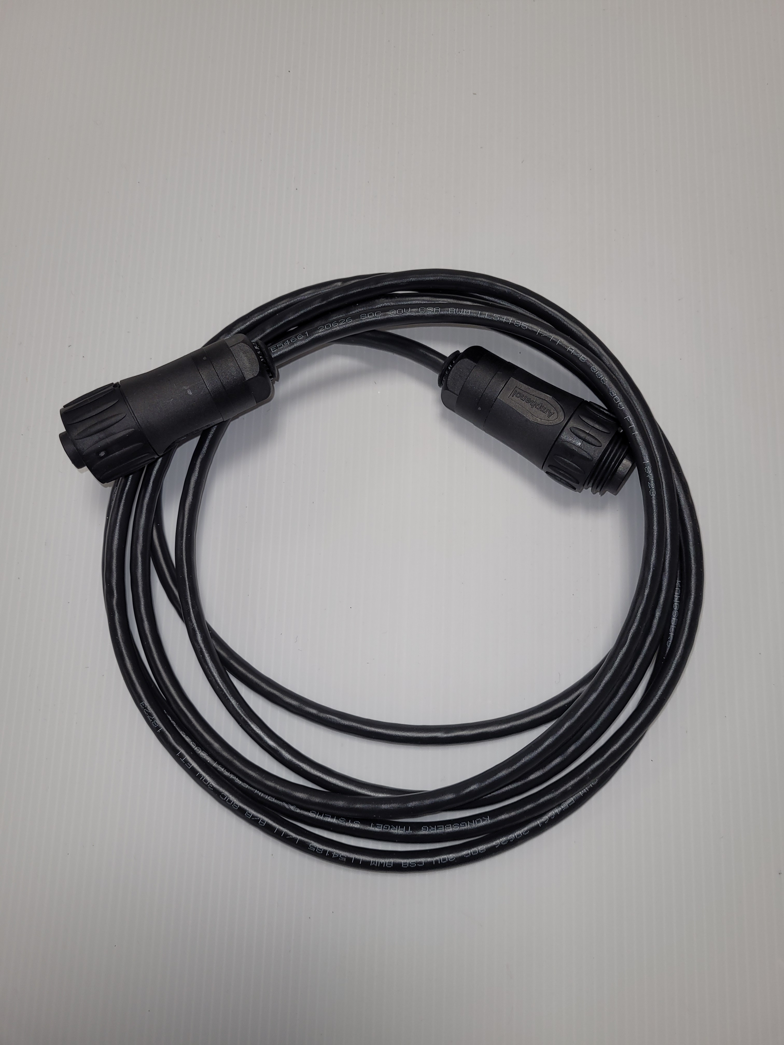
All taget cables (and targets) have a male and a female connector. Male connectors only mate with female connectors, and vise versa.
Push connectors well together before screwing the screw caps of the connectors together. Only the female connector of the M23 series connectors has a screw cap. Do not rotate the back end of the connectors when connectors are mated, as they might break.
The OpticScore targets are quite power consuming, enabling both target illumination and target lifts. In this respect, every fourth target need to be powered with a separate power supply.
Warning!
Do not attempt to run more then four targets for every power supply.
Power supplies between groups of targets are inserted by use of T-shaped power injector cables (KTS part no: 13100002 (Amphenol) and 13100004 (M23)). Targets in front of, and at the back of a separate powersupply will stay signally interconnected.
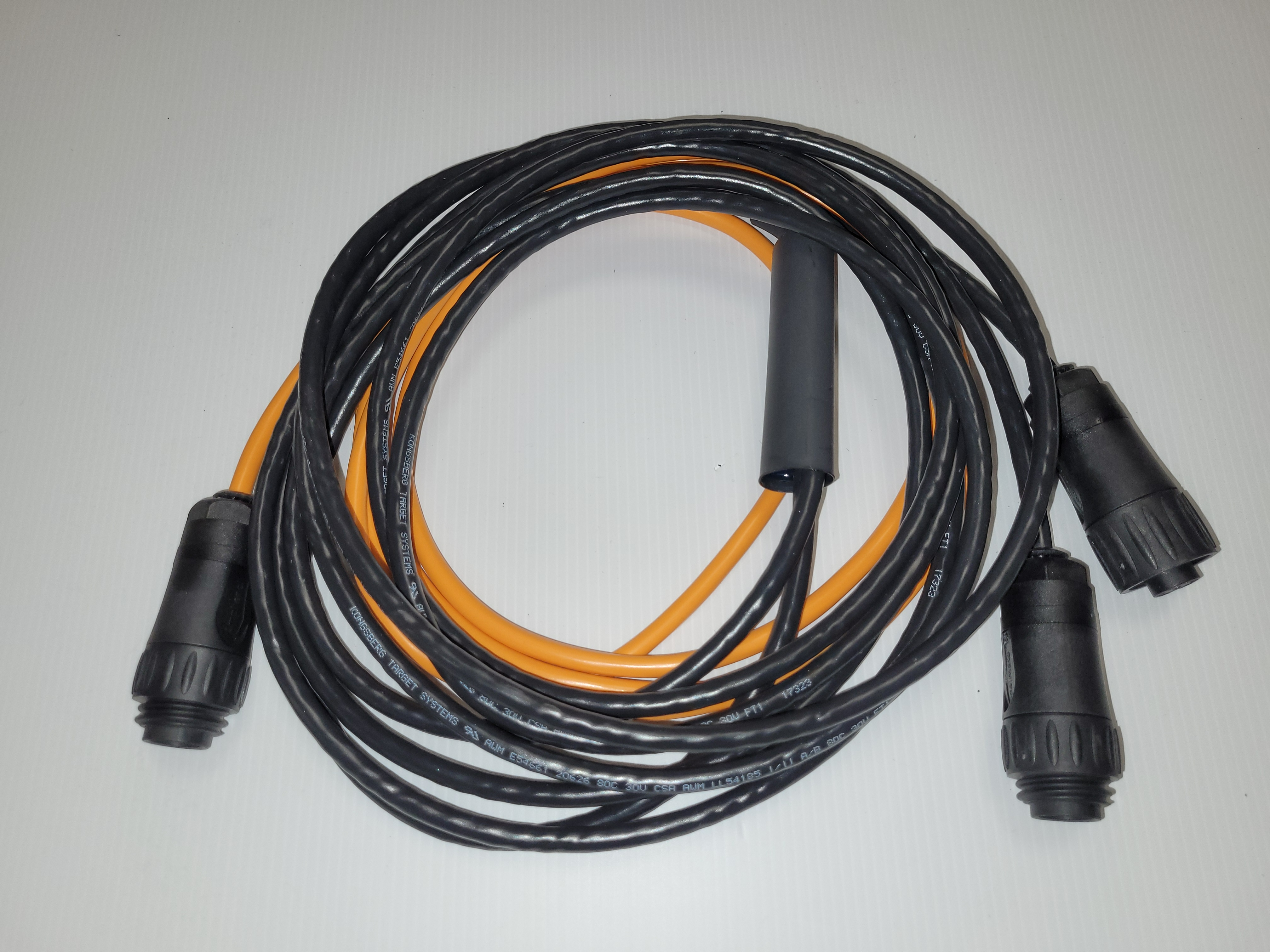
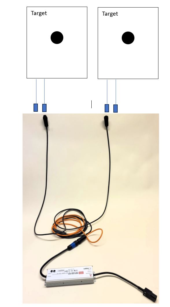
Targets, power injector cable and separate power supply are connected as illustrated above. Note that the orange end of the power injector cable is always connected to the power supply. Black ends connected to targets.
NOTE - first time installation!
Always start interconnecting targets from the power supply cabinet, to avoid interconnection challenge, as all targets and cables are fitted with male and female connectors.
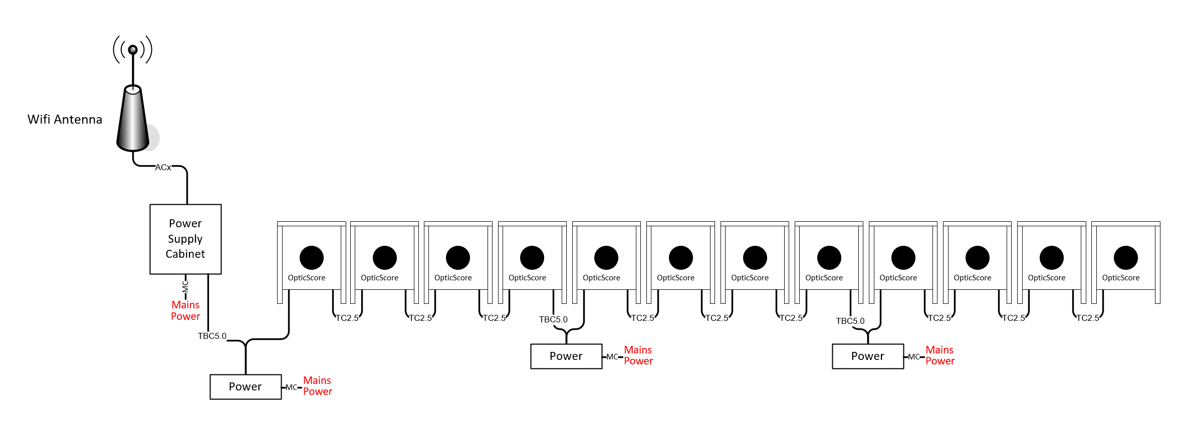
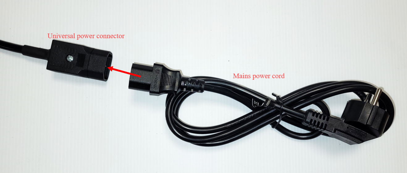
Cabinets and power supplies are fitted with a universal power connector. They must be connected to an enclosed power cord that should fit national standard power sockets. All KTS supplied equipment connected to mains power handle both 110VAC and 220VAC mains voltage.
Installing WiFi antenna
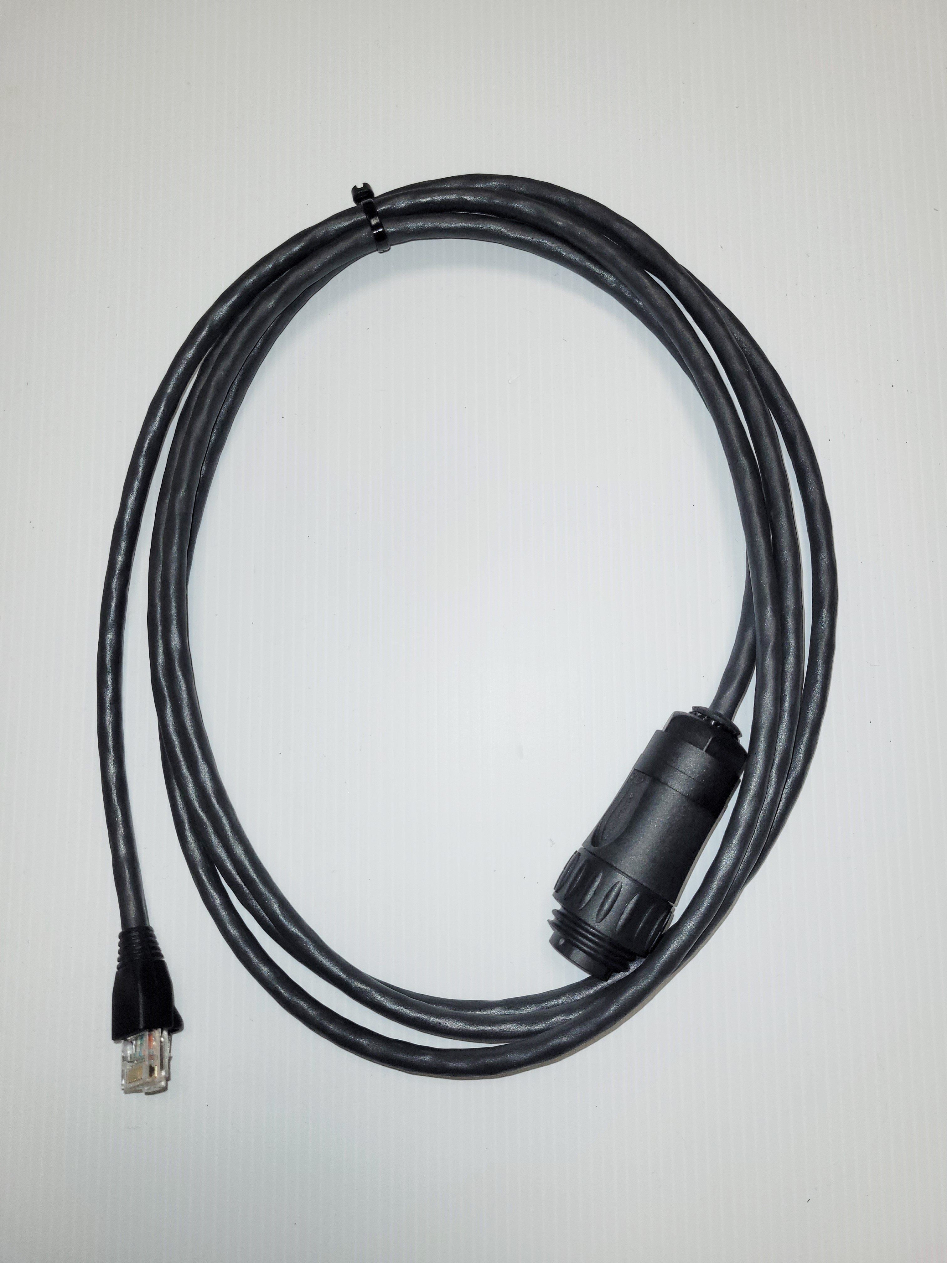
If the system is supplied with WiFi connection to firing line (monitor tablets and/or compunter), the WiFi antenna need to be installed in proximity to the power supply cabinet, though depending on the length of the antenna cable. Antenna cables may be supplied in different lengths.
 |
 |
The antenna cable is connected to the antenna (the lid at the back of the antenna need to be opened to do so). Antenna cable is also connected to one of the tree available connectors inside the power supply cabinet.
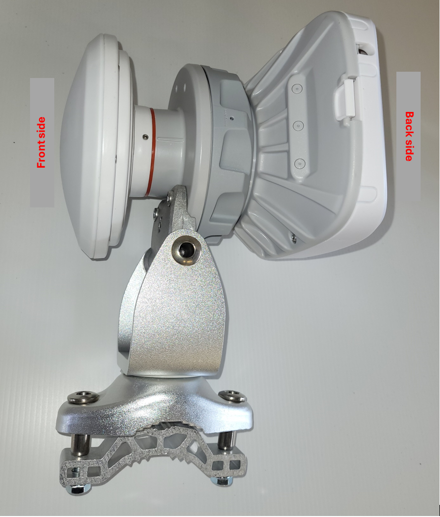
The antenna is installed to face the centre of monitor tablets and computers. The antenna will perform best if intalled somewhat above floor, with as few obsticles as possible between antenna and WiFi connected units.
Note!
The antenna has a 90 degree beam (radiation) angle. All monitor tablets and computers (connected to the WiFi network) need to be included inside the beam zone.
As an example: The WiFi antenna in use, installed at center line of a 10m shooting range, facing directly towards the firing line, would cover a 20m wide firing line. Bigger shooting ranges will require a better planned WiFi antenna installation, thus possibly a long(er) antenna cable.
Wast shooting ranges may be fitted with several WiFi antennas to cover larger areas or separated zones.
Turning on/off the scoring system
Target line are started by applying mains power to the mains power connectors. The system is shut down by switching off mains power.
Tip!
It is fine, for indoor scoring systems, to provide a separate power coarse for the system in target line - controlled by a switch at firing line. This will ease power ON/OFF of system. Consider power requirements when doing so for huge target systems.
Work at mains power grid should always be performed by qualified personnel.
Monitor tablets are started and shut down as tablets normally are started and shut down. KTS provided tablets will automatically start the scoring application when tablet is switched on. Tablets with Windows operating system may in addition be shut down from the eStatus application at the eHub.
Here's a link to KTS' YouTube channel how to use and operate the eScore system.
Connecting the scoring system to a computer
Computer(s) may be connected to the scoring system. This is done by WiFi or cable. The latter is recommended for several lane systems running competitions.
If the power cabinet is fitted with an eHub device, eScore applications are available. That is control room application, status funtionality, upgrade facilities etc. These are accessed with an ordinary internet browser at computer or tablet.
Access from the inside of the eScore network
Access can be given through the eScore WiFi network. WiFi name and password are marked at the back of the WiFi antenna.
To connect computer by cable, a normal ethernet patch cable is connected between the computer and the network switch inside the cabinet. Any unused port of the switch(es) may be used.
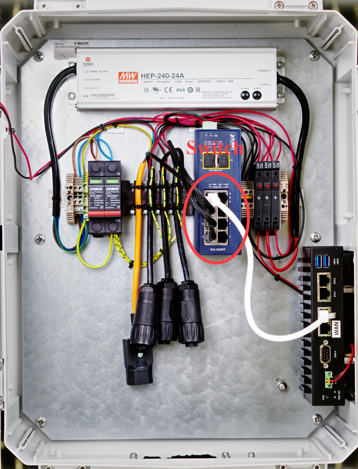
eScore applications are accessed with an ordinary internet browser at computer or tablet. Enter the IP-adress of 10.10.0.1 in the browser field to get access.
Access from outside the eScore network
If the eScore system is connected to a separate (Shooting Range) LAN (Local Area Network), the eScore applications may be accessed from any computers connected. See next chapter how to connect the eScore system to an other LAN.
In these cases the eHub of the eScore system is given an IP-adress by the router of the LAN. eScore applications is accessed with an ordinary internet browser at computer or tablet. Enter the given IP-adress in the browser field.
Here's a link to our YouTube channel how to use and operate the eScore system.
Connecting a printer to the eScore system
To get printouts a printer need to be connected to a computer that is connected to the system. Printers can not be connected directly to the ethernet of the system.
Connecting the system to internet and/or local network.
If the system is fitted with a so called eHub device (typically installed in a power supply cabinet), the system may be connected to internet and/or separate LAN (local area network - i.e. Shooting Range network).
This is done by connecting internet/LAN to the unused WAN port of the eHub device, with an ordinary ethernet patch cable.
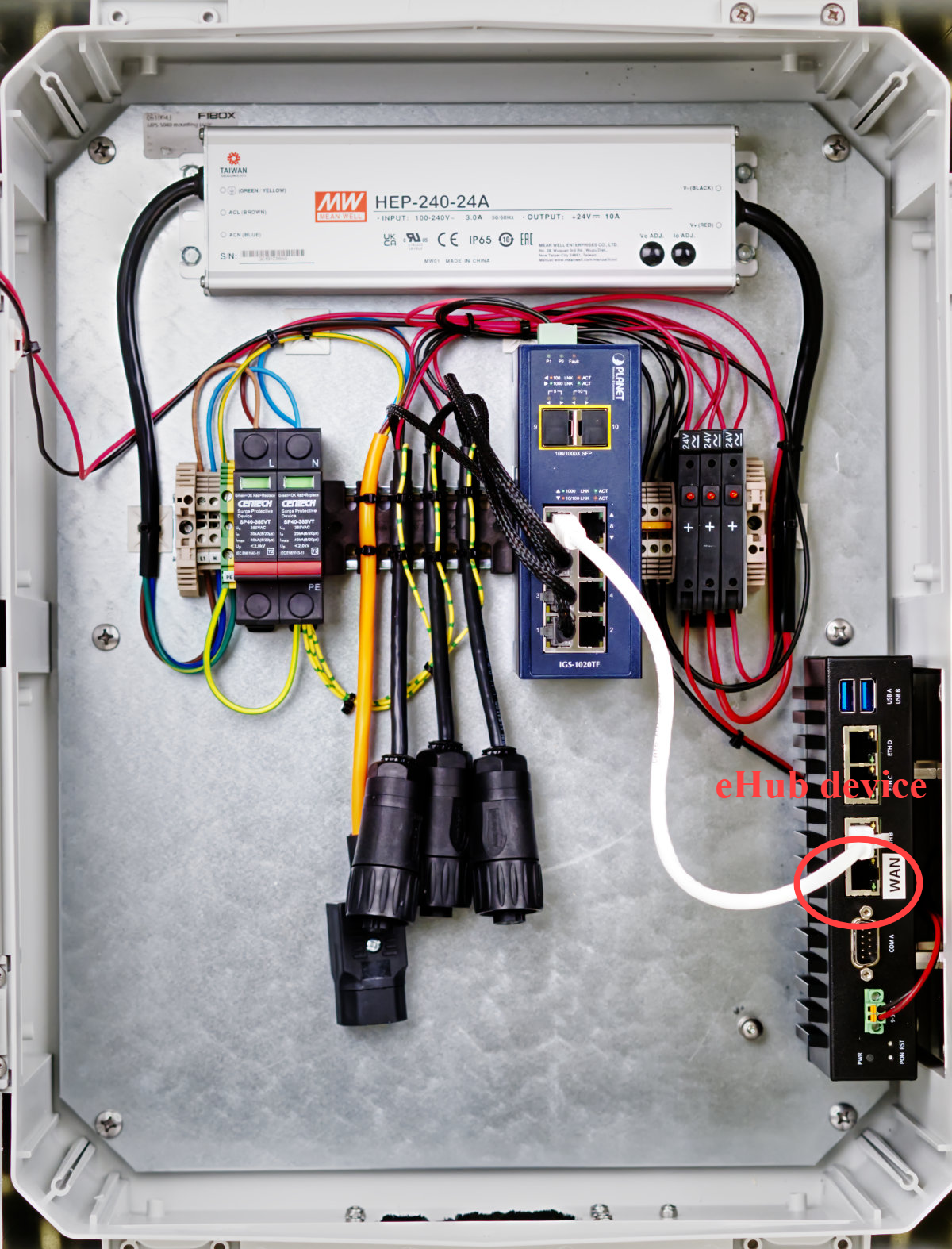
Warning!
Do not connect internet or separate LAN anywhere else in the eScore system than to the WAN port, as this will cause system malfunction.
By connecting the system to internet, the eScore system will automatically download new SW upgrades, new target definitions and new shooting programs. Also, the system will automatically upload scores to KTS cloud services for live internet presentation ( http://live.kongsberg-ts.no/ ) and store scores for shooter journal.
Note!
Live internet presentation is subjected to annual license agreement. Utilization of shooter journal require shooter pre-registration in KTS Cloud service (Link - how to register) (Link to YouTube video).
Ranking
Coputers for ranking (running ranking software) are typically connected to shooting range network, that is concequently typically connected to the WAN port of the eHub.
Warning!
Ethernet cables can never be more than 100meters.
Target lift positions
Target lift positions
The system has predefined default heights for prone, kneeling, and standing positions. It is important to adjust these to the heights recommended by your organization. If the targets use a bullet catcher, it is crucial that the different target lift positions are aligned with the bullet catcher for each position.
Adjusting the Target Lift Positions
In the Settings → Range Setup, there is a section for "Target Lift". Enter the correct heights for the different positions, then click "Save". The new setup will be synced to the targets immediately. The target lift will automatically adjust if the height of the current position is changed.
