Introduksjon OpticScore eScore
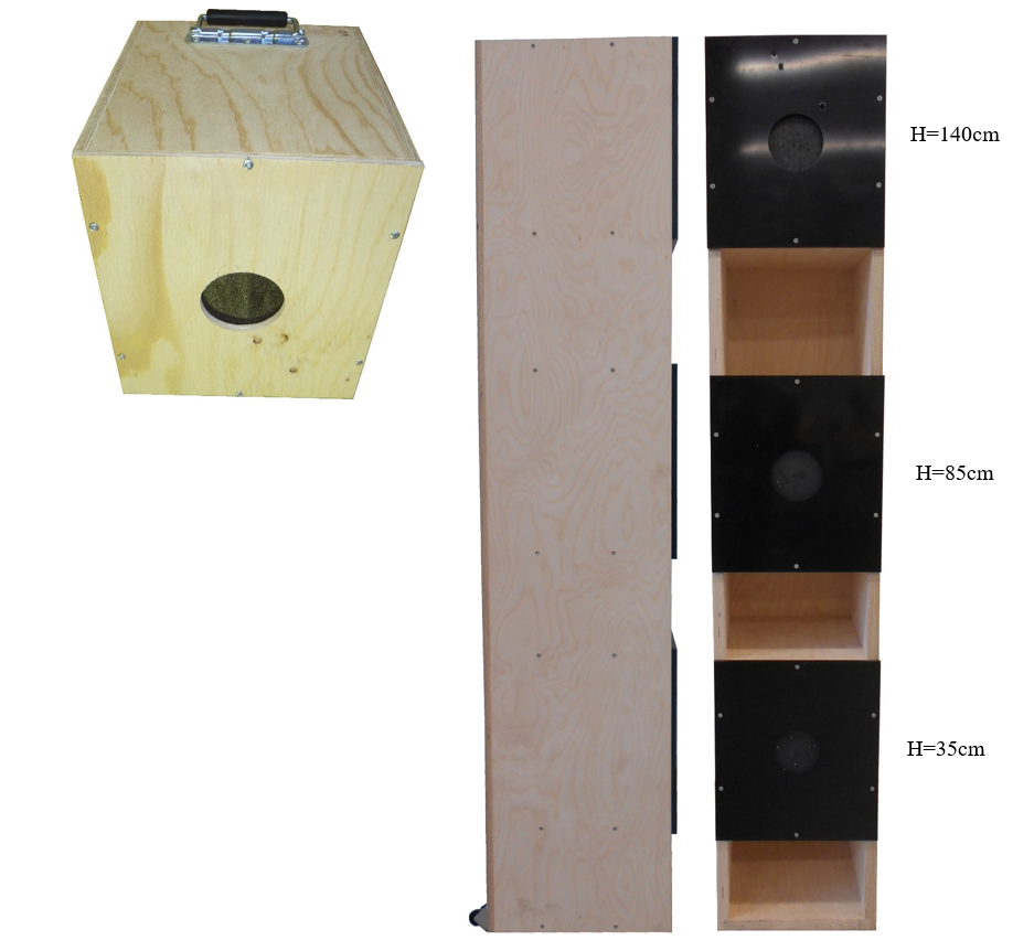
eScore OpticScore-skiven er nyeste generasjons elektronisk skivesystem med optisk skuddregistreringsteknologi. Kameraer inne i skiven registrerer kulen presist. Skiven anbefales for innendørs skyting med 4,5mm luftvåpen og .22LR. Skiven kan leveres med skiveheis, som gir mulighet for forskjellige skytehøyder (stående, knestående og liggende). LED-belysningen er justerbar fra standplass, slik at lysstyrke og farge kan tilpasses skyteforhold og personlige preferanser.
Nøkkelinfo for eScore OpticScore
Presis deteksjon – eScore OpticScore har en ISSF fase 1-godkjenning.
Passer for kortdistanse (10–15 m) .22LR og luftgevær.
Kompakt størrelse, rask oppsett.
Bredt utvalg av sikteblinker (fysiske) og blinkdefinisjoner (på skjermen).
Enkelt å bytte ut sikteblink.
Lavt vedlikehold.
Skiveheis tilgjengelig.
Justerbar belysning fra standplass (intensitet og fargevalg).
Tekniske spesifikasjoner og dimensjoner
| Temperaturområde | 0 til +40 °C |
| Vekt | 3,5 kg (kun skiven) 8 kg (skive med beskyttelsesplate) 13,5 kg (skiveheis) |
| Strømforbruk | ~ 17 W @ 48 VDC (med maks belysning) ~ 50 W @ 48 VDC (Aktiv skiveheis, belysning på) |
| Godkjente kalibre | 4,5 mm luft og .22LR. |
| Anbefalt bruk | 10–15 m luftpistol/luftgevær 10–15 m .22LR rifle |
| Anbefalt driftsspenning | Typisk 48 V (Kan fungere i området 24V–48V) |
Dimensjoner
| A: 470 mm | 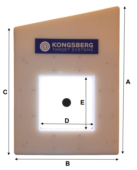 |
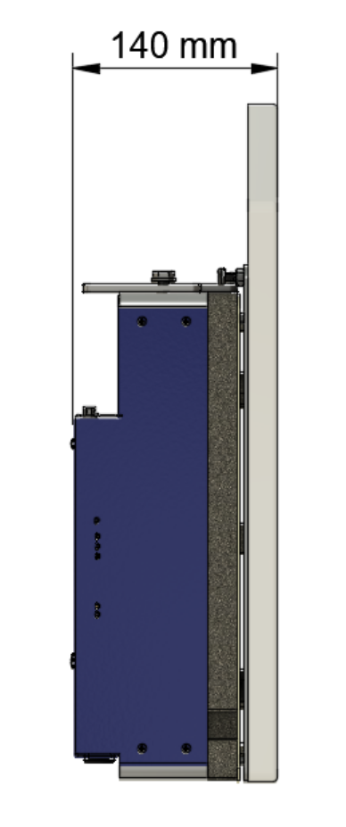
|
| B: 400 mm | ||
| C: 330 mm | ||
| D: 170 mm | ||
| Ø: 170 mm |
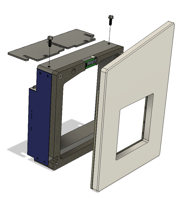
eScore OpticScore exploded view and partslist
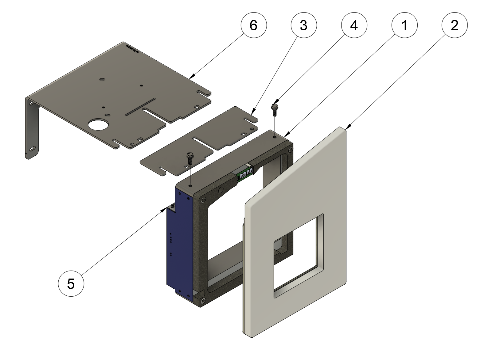
Exploded view Below is an exploded view of the common components used in the eSco...
Exploded view / Sprengskisse
Part list
| ID | Description / Beskrivelse |
| 1 | eScore OpticScore Target |
| 2 | Protection plate with illumination / skivepansring med belysning. |
| 3 | Illumination bracket / belysningsbrakett |
| 4 | Mounting screws and washer (M8) / Skivemonteringssbolter m/ boltskiver. |
| 5 | eScore OpticScore Target electronics housing (wiring not shown)- options with different connectors are available / eScore OpticScore skivelektronikkinnkapsling. Kabling ikke vist, flere opsjoner tilgjengelig. |
| 6 | Optional: Wall mount / bullet catcher bracket / opsjon: veggbrakett og kulefangerbrakett. |
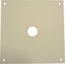
Tilgjengelige sikteblinker til OpticScore
Available mask targets for OpticScore
The OpticScore target can be fitted with different mask targets/front templates:
| KTS part number: | Name | Spot size / comment |
| 97020797 | ISSF 10m air rifle | Ø 30.5mm |
| 97020798 | ISSF 10m air pistol | Ø 59.5mm |
| 97020810 | DFS 15m rifle | Ø 38mm |
| 97020848 | NSF 15m rifle | Ø 34.2mm |
| 97020879 | DGI 15m air rifle | Ø 42.75mm |
| 97020880 | DGI 15m pistol | Ø 100mm |
| 13020442 | Finfelt Hjul | NOR terrain 15/100 scale |
| 13020446 | Finfelt Mini 1/9 | NOR terrain 15/100 scale |
| 13020447 | Finfelt Mini 1/3 | NOR terrain 15/100 scale |
| 13020448 | Finfelt Stripe | NOR terrain 15/100 scale |
| 13020449 | Finfelt C15 | NOR terrain 15/100 scale |
| 13020450 | Finfelt 1/10 | NOR terrain 15/100 scale |
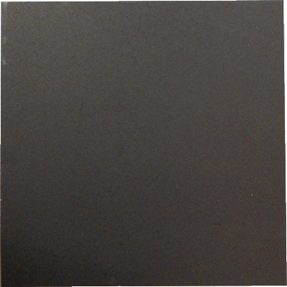
The target may also be fitted with a black cardboard backer / witness plate (KTS part no: 97020801).
Vedlikeholdskrav for eScore OpticScore
Selv om eScore OpticScore-skiven nesten er vedlikeholdsfri, kan miljøet på skytebanen være utfordrende grunnet små partikler fra kuler og papirblinker. Dette medfører noe vedlikehold, som bør gjøres for å opprettholde skivens nøyaktighet.
Ved å gjøre tiltak for å redusere støvmengde på skytebanen kan vedlikeholdet av skivene reduseres.
Merk : Vær svært forsiktig så du IKKE berører speilene eller glasset i skiven når du håndterer OpticScore-skiven. Fingeravtrykk, riper eller andre skader på de optiske deteksjonsflatene godtas ikke som garantikrav. Observer og følg anbefalingene knyttet til rengjørings- og håndteringsprosedyrene i dette kapittelet nøye, inkludert å IKKE blåse støv og papirrester ut av skiven manuelt (med munnen).
Bytte sikteblink
Utskifting av sikteblink gjøres når blinken ikke lengre gir skytteren en god silhuett å sikte på, eller det ønskes en annen blink.
Nødvendig verktøy: Ingen
Nødvendig utstyr: Ny blink, mikrofiberklut, blåsebelg.
Trinn 1:
Ta av skivepansring. Den henger på belysningsbraketten eller kulefangeren/veggmonteringsbraketten med to M8-skruer med panhode festet i skivepansringa. Vipp bunnen av skivepansringa bort fra skiven til magnetene løsner, og løft deretter opp skivepansringa.
Sørg for at komponentene på baksiden av skivepansringa ikke blir skadet ved å plassere den på en flat og stabil overflate mens du arbeider på skiven.
Videoen nedenfor viser de anbefalte bevegelsene for demontering av skivepansringa.
Trinn 2:
Fjern den gamle blinken og resirkuler den
Trinn 3:
Fjern eventuelt rusk om nødvendig – se neste kapittel for retningslinjer
Trinn 4:
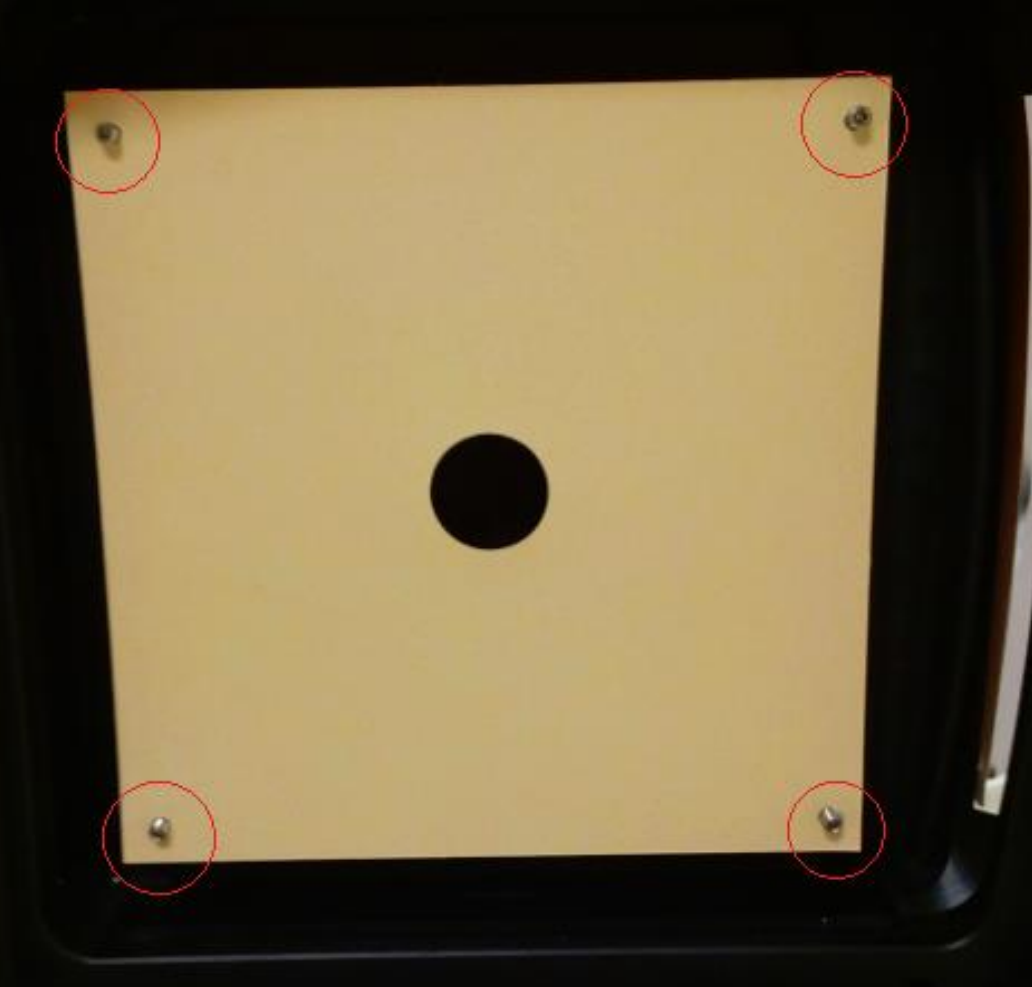
Sett inn den nye blinken fra forsiden av skiven. Heng opp blinken ved å tre blinken inn på de fire skruene som sitter i hvert hjørne av skiven. Skruene er laget litt fleksible for å kunne stramme opp blinken. Det anbefales å feste ett og ett hjørne, og legg et press på de fleksible pinnene for å trekke de mot senter når papirblinken føres på pinnen.
Det er svært viktig at blinken sitter helt rett og flatt etter installasjon - strekt mellom de fire festepunktene. En blink som buler kan føre til komplikasjoner med de optiske sensorene.
Hvis du bruker svart bakgrunn eller verifiseringspapir
Et nytt bakgrunns-/verifiseringspapir kan installeres ved å skyve det inn/ut fra baksiden av skiven som illustrert: 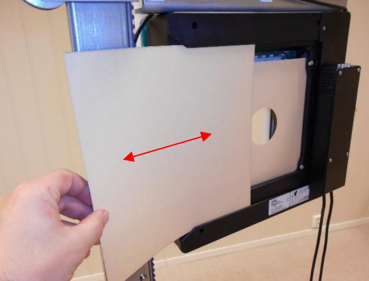
Trinn 5:
Sett skivepansringa på plass igjen. Vær forsiktig så du ikke skader komponentene på baksiden! Se videoen nedenfor for en illustrasjon av hvordan du monterer platen riktig.
Kontroller at belysningen lyser etter montering av skivepansringa!
Dette kan ta noen sekunder etter at den er slått på. Hvis belysningen ikke har tent etter 30 sekunder, må du bekrefte at det er strøm på skiven ved å inspisere OS-LED-en på siden av skiven. Hvis strømmen er på (OS-LED blinker) og belysningen er av, verifiser at kontaktfjærene på skiva kommer i kontakt med kontaktflatene på skivepansringa.
Kritiske overflater, fjerning av rusk eller partikler
Advarsel
Pass på at du ikke skader speilene eller glassplatene inni skiven! Fingeravtrykk eller riper vil redusere nøyaktigheten!
Papirpartikler eller annet rusk på overflatene inne i skiven kan redusere nøyaktigheten. Det anbefales derfor å fjerne rusk når du bytter ut sikteblinken. Dette bør gjøres med lett trykkluft.
Advarsel
Kompressortrykkluft skal ikke brukes, og det skal IKKE blåses luft manuelt! Dette kan etterlate rester av kompressorolje eller spytt som vil korrodere på speiloverflatene.
En luftblåser for kameralinsen bør brukes. Den etterlater ikke rester eller har for høyt trykk:
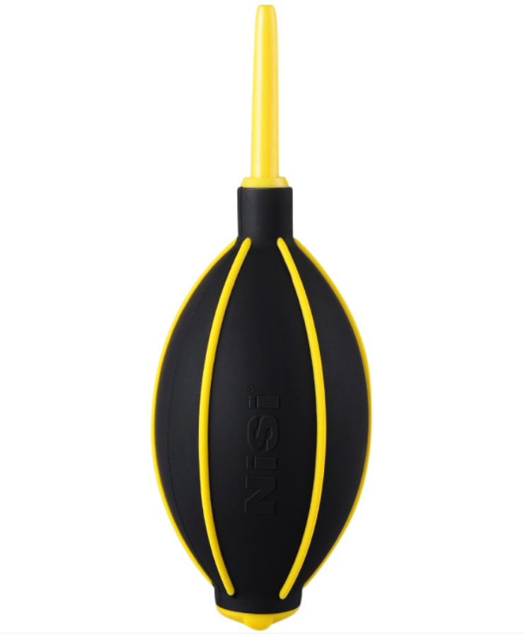
Speilene er forsølvet. Rengjøring av speilene bør kun gjøres KUN når det er nødvendig for å bevare egenskapene deres. Hver rengjøring vil føre til noe minimal slitasje på speiloverflaten.
Ved rengjøring av speil og glassflater må følgende gjøres:
- Fjern papirbiter forsiktig med luft (se verktøyet ovenfor)
- Tørk forsiktig bort gjenværende rester med en ren mikrofiberklut for glass. Dersom speilene må renses, må mikrofiberkluten være HELT ren, enhver form for forurensning vil kunne ripe opp speilene.
- Om nødvendig kan en fuktig mikrofiberklut for glass brukes, vridd så tørr som mulig, men gjenværende fukt på overflatene må unngås.
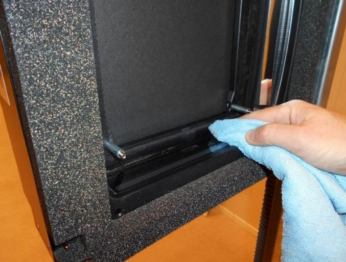
Synlig korrosjon på speiloverflatene
Hvis det er synlig korrosjon eller annen forurensning på speilet, kan en IKKE-SLIPENDE sølvpleiekrem brukes til å polere det. Vær svært forsiktig og ikke puss mer enn nødvendig!
Sørg for å følge prosedyrene ovenfor, og sørg for å fjerne aller rester av sølvpleieprodukter etter rengjøring.
Rengjøring eller behandling av speil anbefales ikke med mindre det er et klart behov.
Krav til lagring
Lagring av OpticScore-skiver
eScore OpticScore-skiven må oppbevares i et rent og tørt miljø (<50 % luftfuktighet) ved temperaturer over 10 °C. Dersom det er mye støv eller partikler i luften eller omgivelsene der skiven lagres, bør skiven tildekkes slik at glass- og speilflatene i skiven ikke utsettes for høy grad av forurensning.
Tilleggsutstyr
Det finnes en rekke tilleggsutstyr som kan bestilles med OpticScore - eScore-skiven. Disse er listet opp her:
Veggfeste / kulefangerbrakett
eScore OpticScore har en veggmonteringsbrakett tilgjengelig, som også kan fungere som et feste for kulefangeren for luftvåpen. Braketten har et senterlinjemerke som er på linje med midten av skiven (i høyden). Dette er nyttig når du monterer skiva i en bestemt høyde på skytebanen. Braketten leveres med fire hull på baksiden, for skruer som kan brukes til å feste skiven til veggen. Bruk et vater eller lignende når du monterer braketten på veggen for å sikre rett montering.
Dersom det ikke benyttes kulefanger for luftkaliber (opsjon) må det være kulefanger bak veggen,
Tips!
Fest veggfestebraketten til veggen før du fester skiven til braketten.
Vær oppmerksom på at denne braketten alltid brukes når du bruker kulefangeren til luftkalibre, selv om skiven ikke er montert på en vegg (dvs. skiver brukt med skiveheis).
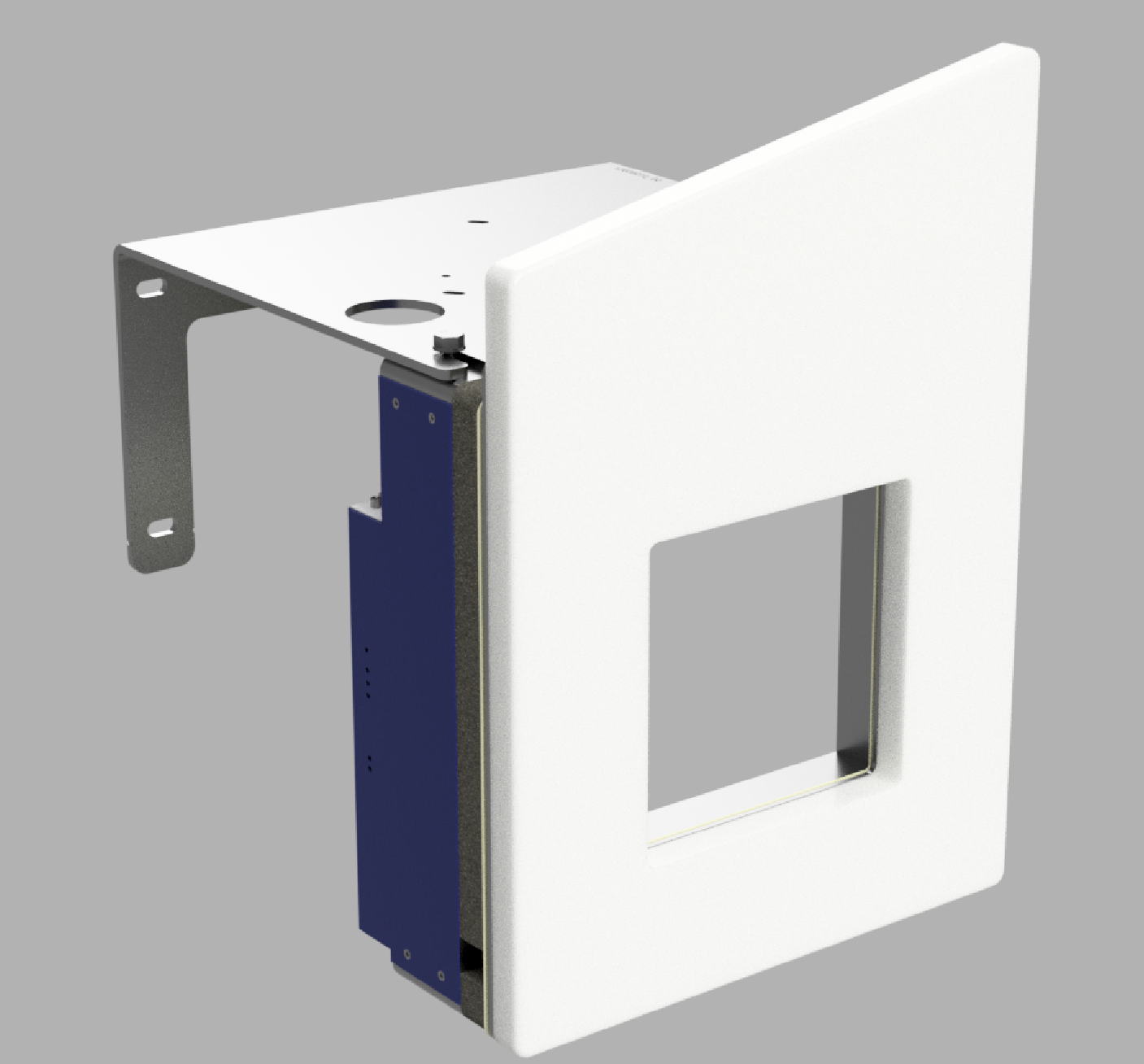
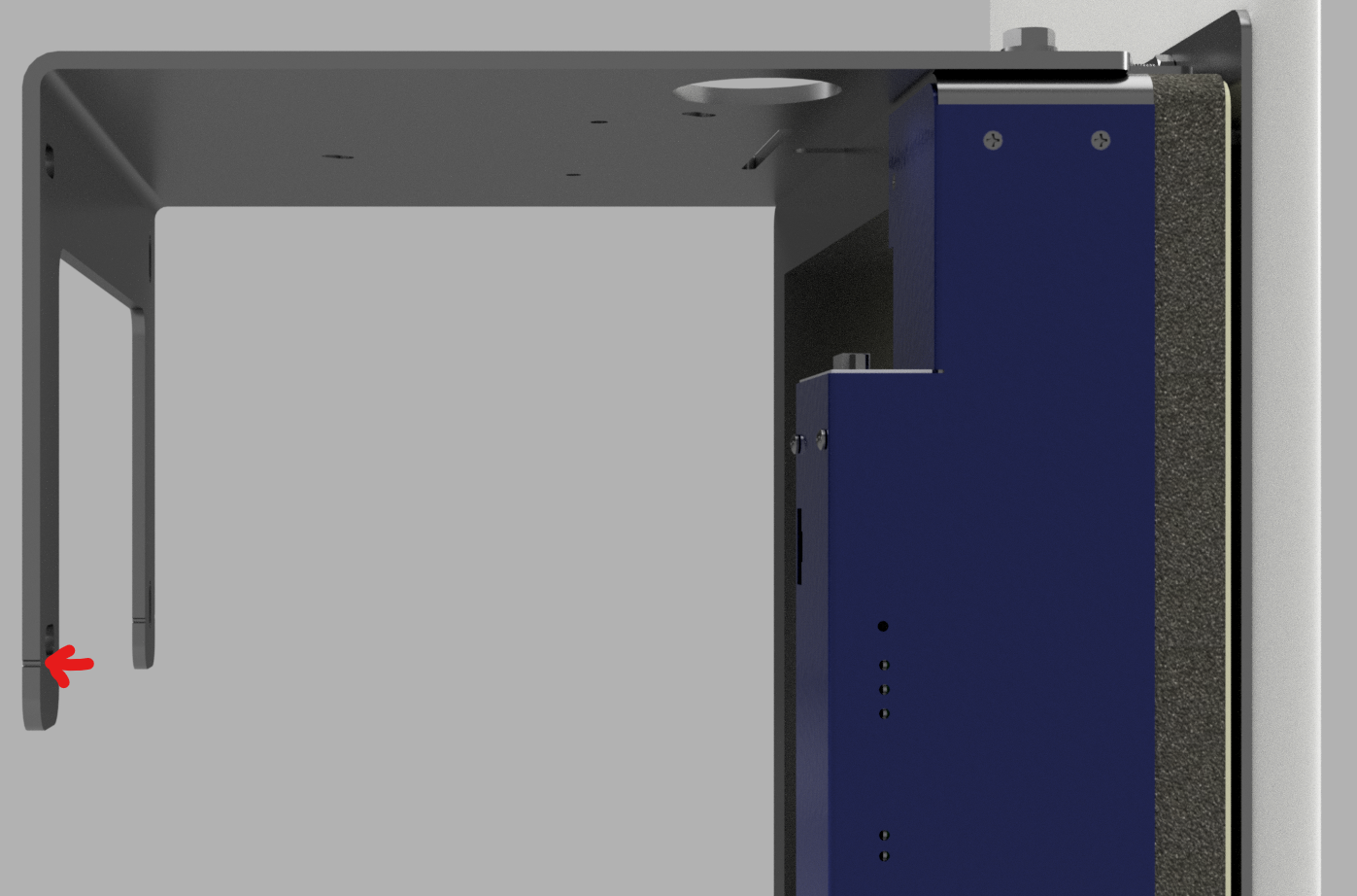
Veggfestet/kulefangerbraketten festes til skiven på følgende måte:
- Fjern skivepansringa (se vedlikeholdskapittelet for veiledning)
- Løsne de 2x M8 sekskantskruene på toppen av skiven litt.
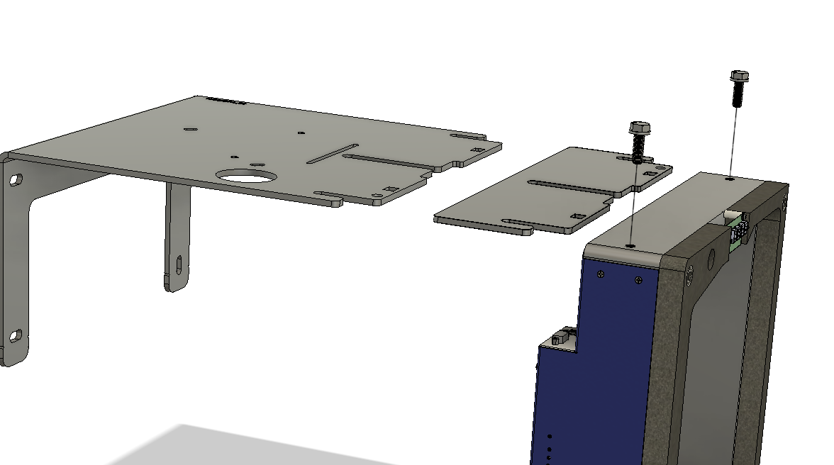
Merk at hvis skiven er festet til en skiveheis eller et veggfeste, må ikke disse boltene løsnes helt! Dette kan føre til at skiven faller ned og skades.
- Bytt belysningsbraketten med veggfestebraketten – sørg for at boltskivene er plassert oppå braketten og ikke under.
- Stram skruene (ikke bruk for mye kraft, gjengene i skiva er plast!)
Note!
Sørg for at skiven er skjøvet helt inn i sporet på braketten.
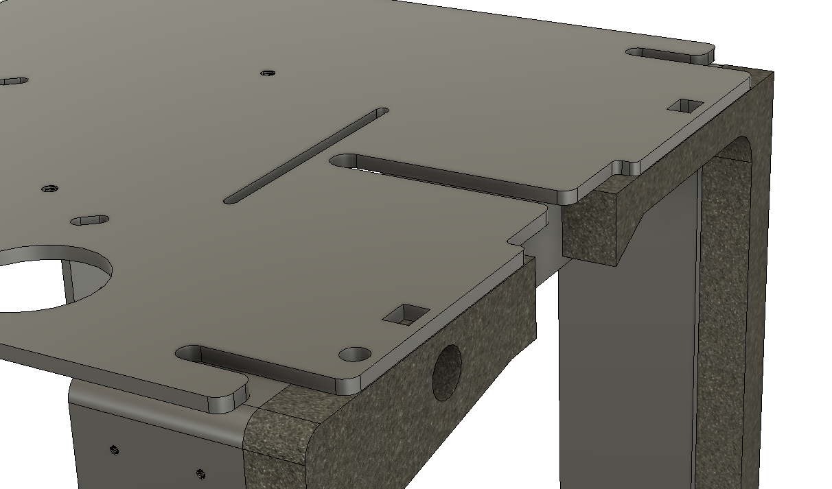
- Monter skivepansringa igjen (se vedlikeholdskapittelet for veiledning).
4,5 mm kulefanger for luftvåpen.
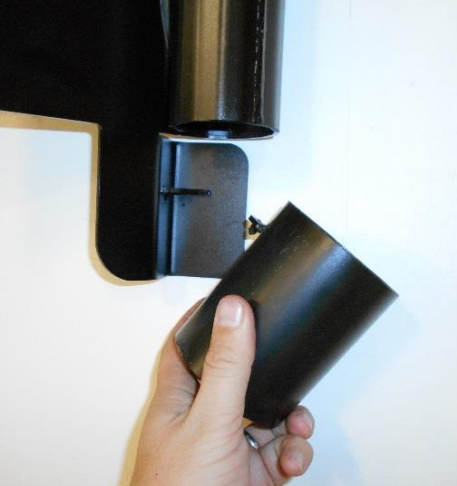
En valgfri kulefanger for luftgevær er tilgjengelig, KTS delenummer 33 07 004 – merk at du må ha veggfeste/kulefangerbrakett (KTS delenummer 13020272) for å kunne montere kulefangeren riktig på skiven. Braketten kan også brukes med skiveheis. Kulefangeren må festes til braketten. Bruk de medfølgende mutterne og boltene, som vist på illustrasjonene nedenfor.
Advarsel!
Denne kulefangeren må IKKE skytes på med annet enn kjegler i kaliber 4,5 mm.
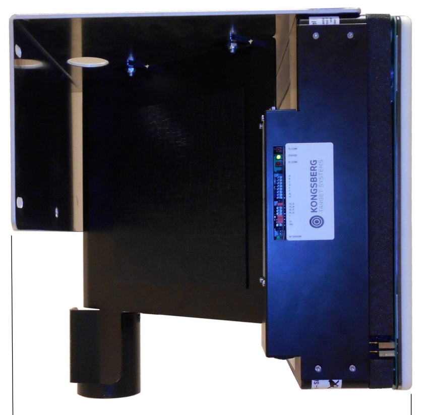
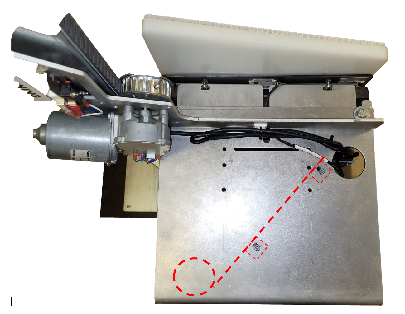
Merk at skiven som brukes på bildet ovenfor er en annen variant av OpticScore, men bildet illustrerer hvordan kulefangeren er festet til braketten. Bildet nedenfor illustrerer også hvordan kulefangeren er plassert inne i braketten (røde stiplede linjer).
Beskyttelsesplate for rikosjett fra luftvåpen
Kjegler fra luftvåpen kan sprette tilbake mot skytterens posisjon hvis de bommer på treffpunktet og treffer skivepansringen i plast. For å forhindre dette kan en rikosjettbeskyttelsesplate (KTS delenummer 97020813) festes til skivepanseret. Den er festet med fire plastknapper (KTS delenummer 1507002).
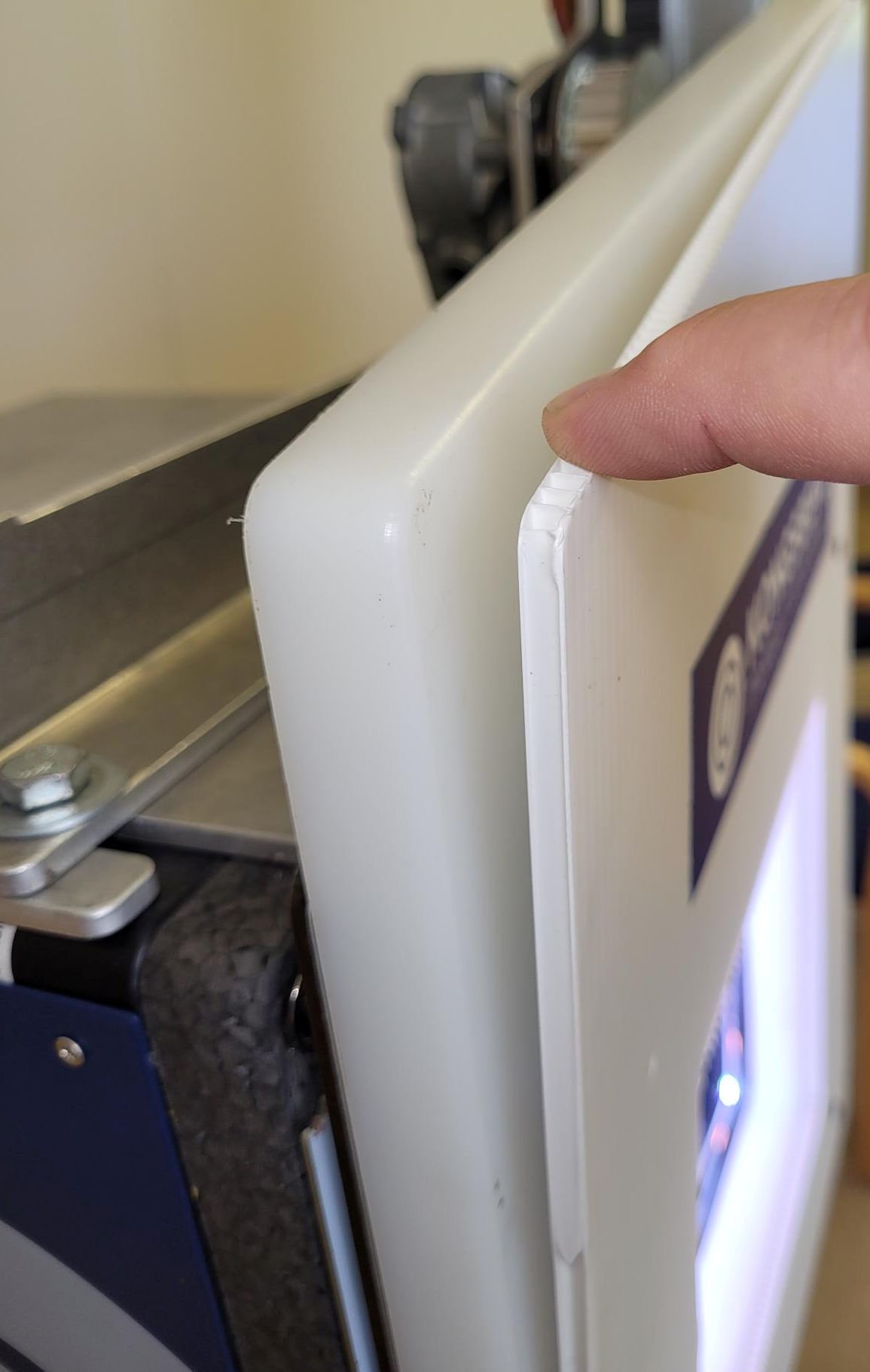
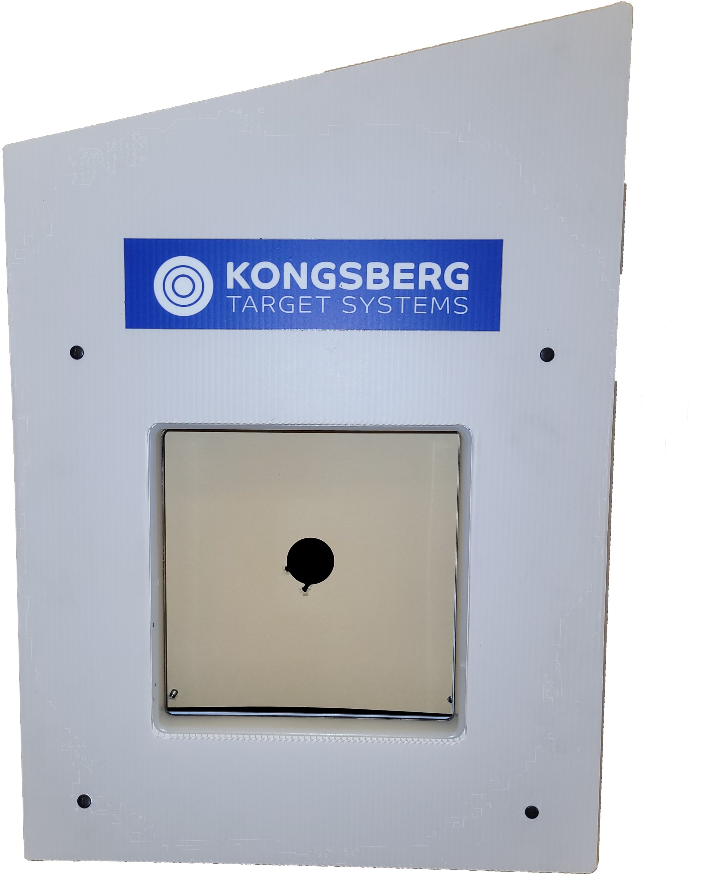
Denne platen kan håndtere et begrenset antall skudd, og må derfor byttes ut når den ytre overflaten er nedslitt. Kjeglene fanges opp inne i platens ytre overflate.
Skiveheis
eScore OpticScore Skiveheis
Skiveheis er tilgjengelige for opticScore eScore-skiven. Noe montering er nødvendig på skytebanen ved første gangs bruk, og dette er beskrevet her.
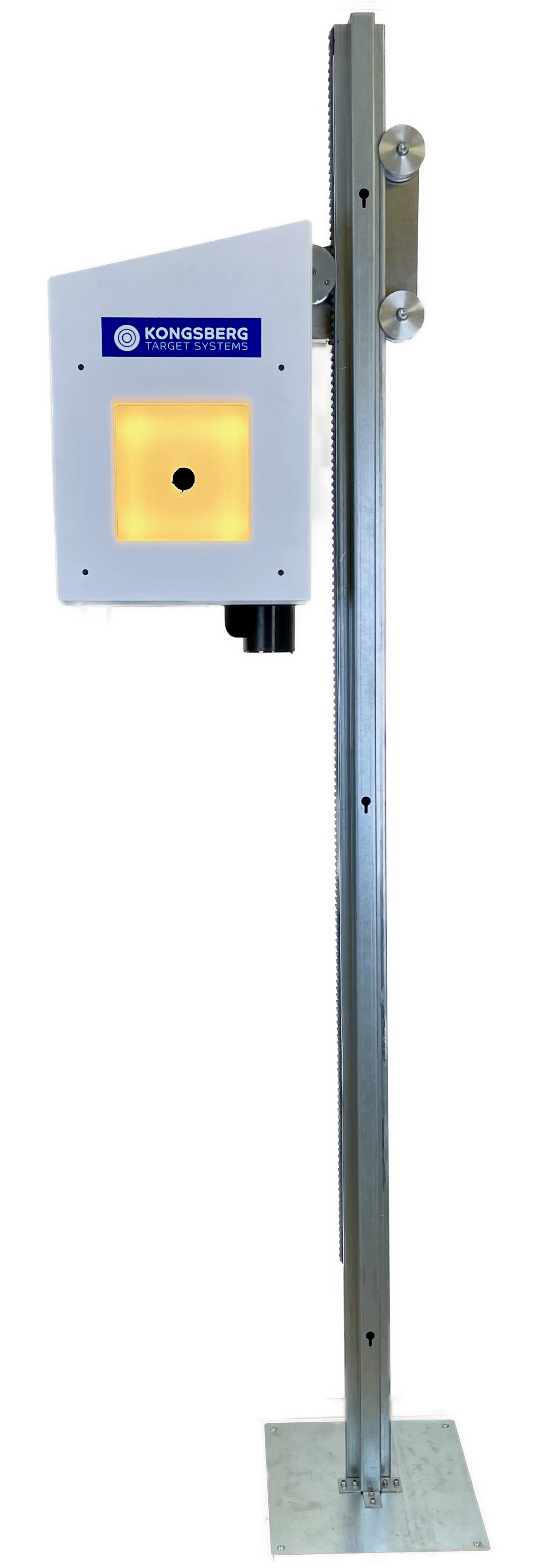
Monteringsanvisning
| Monter bunnplaten til heis-stangen med de medfølgende mutterne, boltene og skivene. | 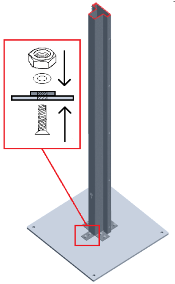 |
|
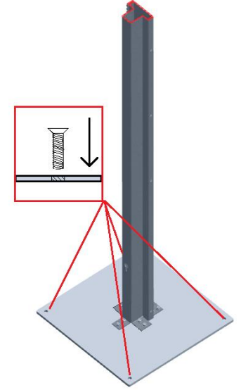
Monter bunnplaten til gulvet (eller annen passende plattform) med passende festemidler for det valgte materialet. Advarsel!Dette må gjøres før målet monteres på skiveheisen!
|
 |
| Monter endestoppbraketten med to skruer og fjærskiver. Bruk den øvre posisjonen, IKKE den nedre. | 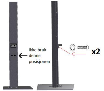 |
|
Fjern det nedre støttehjulet fra løftebraketten. MonteringsinformasjonHusk retningen på den koniske skiven som er montert ved siden av lageret inne i støttehjulet. Denne skiven må settes inn i samme retning og samme rekkefølge i forhold til de andre skivene.
|
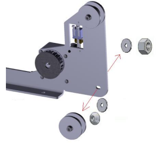 |
|
Roter løfterbraketten og sett den inn på heisstangen. Roter den mot klokken slik at tannhjulet og støttehjulene støtter løfterbraketten. MonteringsinformasjonMonter det nedre støttehjulet, men ikke stram skruene (ennå)
|
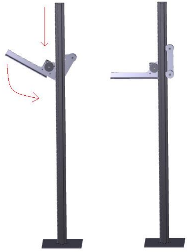 |
Braketten skal nå være omtrent 90 grader i forhold til ryggraden. Juster støttehjulene etter behov. MonteringsadvarselIkke stram skruene på støttehjulene for hardt, da lagrene kan bli skadet.
MonteringstipsDet kreves at det er to personer som utfører dette trinnet.
|
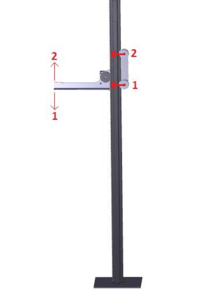 |
|
Installer endestopputløsere på løfterens ryggrad
Fjern beskyttelsen på den dobbeltsidige teipen på baksiden av endestopp-utløserne: 
Tape endestopp-utløserne til de rektangulære merkene på løfterens ryggrad, som vist på tegningen til høyre. Ett merke øverst på ryggraden og to merker nederst. Ikke bry deg om de runde merkene. Vær oppmerksom påMerk at det er to rektangulære merker på den nedre enden av løfteryggen. Bruk det øvre, som vist på tegningen!
Endestopp-utløserne må orienteres spesifikt slik at den ene enden vender oppover (this side up). Se bildet ovenfor.
|
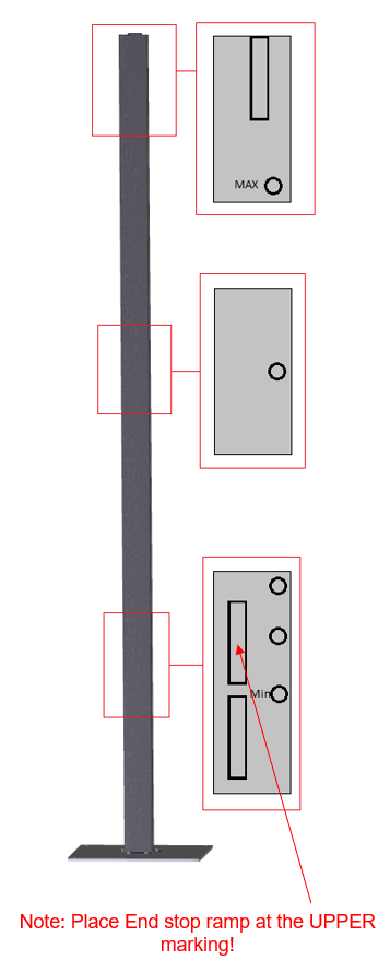 |
| Denne figuren viser endestopp-utløsere og braketten på plass. Ikke bry deg om de små sirklene. |  |
|
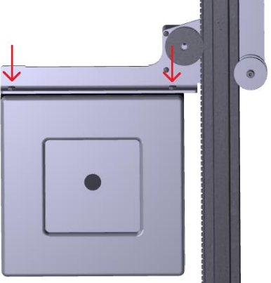
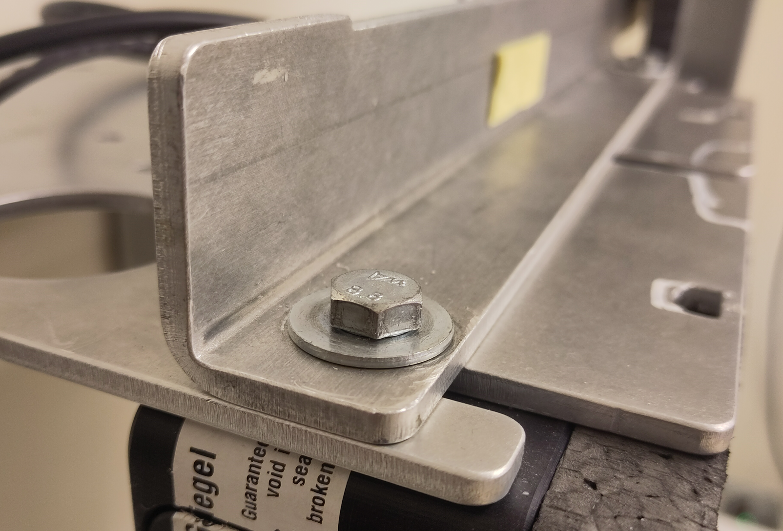
Skiven festes til løftebraketten ved hjelp av de to M8-boltene og skivene (øverst på målet). La det være et lite mellomrom mellom skiverammen og løftebraketten.
Hvis kulefangeren til luftgeværet brukes (og dermed kulefangerbraketten brukes), må du bytte ut den medfølgende belysningsbraketten med kulefangerbraketten i det ovennevnte gapet. Skyv den helt fremover til den hviler mot skruene.
Ellers, hold belysningsbraketten i det nevnte gapet. Skyv den helt fremover, til den hviler mot skruene.
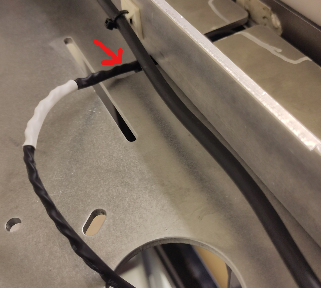
Note!Sørg for at belysningskabelen er plassert i sporet i kulefangeren/belysningsbraketten. Stram de to skruene øverst på skiven, som forbinder alle brakettene og målet sammen. IKKE stram disse skruene for hardt, da dette vil skade skiven. |
   |
|
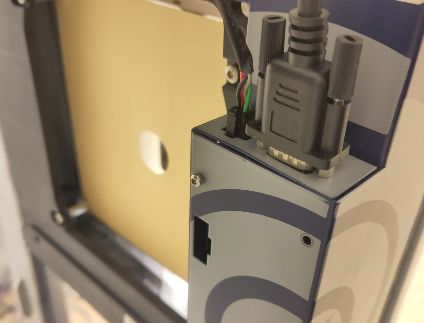
Kabelen fra løftebrakettmotoren er koblet til opticScore-skiven. Belysningskabelen er også koblet til skiven. Bildet til høyre viser begge kablene tilkoblet. |
|
Rikosjettbeskyttelse for skiveheis
KTS delenummer 117 0097 44 0024.
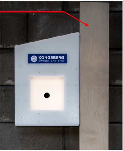
Produktet dekker løftestangen. Brukes kun ved skyting med kaliber .22LR. Dette produktet fungerer som rikosjettbeskyttelse, og reduserer også skader på løftestangen hvis den blir truffet.
Rikisjett-beskyttelsen henges i nøkkelhullene på forsiden av løftestangen. Ved første montering må de tre medfølgende skruene skues delvis inn på baksiden av rikosjett-beskyttelsen. Det er forhåndsborrede hull for skruene.
Kulefangere av gummigranulat
Kulefangere av gummigranulat (KTS-delenr. 107 0097 24 0042) og kulefangere av gummigranulat for 3-posisjonsskyting (KTS-delenr. 107 0097 24 0049) finnes også. Disse kulefangerne er hovedsakelig beregnet for kuler i kaliber .22LR. De kan ikke brukes til kraftigere kalibre.
