
Introduksjon til H1E
H1E eScore-skiven er et neste generasjons elektronisk skive basert på akustiske sensorer. Det fungerer med subsonisk og supersonisk ammunisjon og er designet for å plasseres på 100–200 meters avstand.
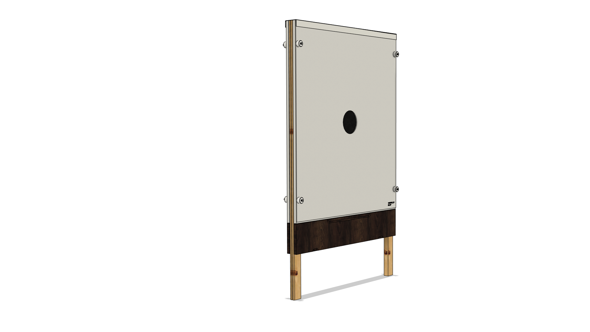
Funksjoner ved H1E-målet
- 4 akustiske sensorer, én i hvert hjørne av skiven
- Horisontale og vertikale gummibånd tilgjengelig
- Manuell rotasjon av gummibånd
- Ekstra pansring anbefales
- Bredt utvalg av blinker er tilgjengelig
- Styrepinnens design muliggjør raskt bytte av blink uten behov for ytterligere nullpunktjustering.
- Kan brukes med både subsoniske prosjektiler som .22LR og supersoniske prosjektiler som .223, .308, 30-06, 6.5
Tekniske spesifikasjoner og dimensjoner
EN |
1160 mm |
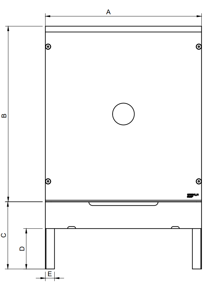 |
B |
1300 mm |
|
C |
500 mm |
|
D |
300 mm |
|
E |
68 mm |
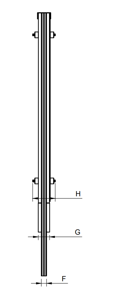 |
F |
36 mm |
|
G |
92 mm |
|
H |
155 mm |
| Temperaturområde | -30 til +60 °C |
| Vekt | ~ 25 kg |
| Strømforbruk | ~ 4 W ved 24 VDC |
| Kaliber | Subsoniske og supersoniske prosjektiler |
H Skive eksplodert visning og deler
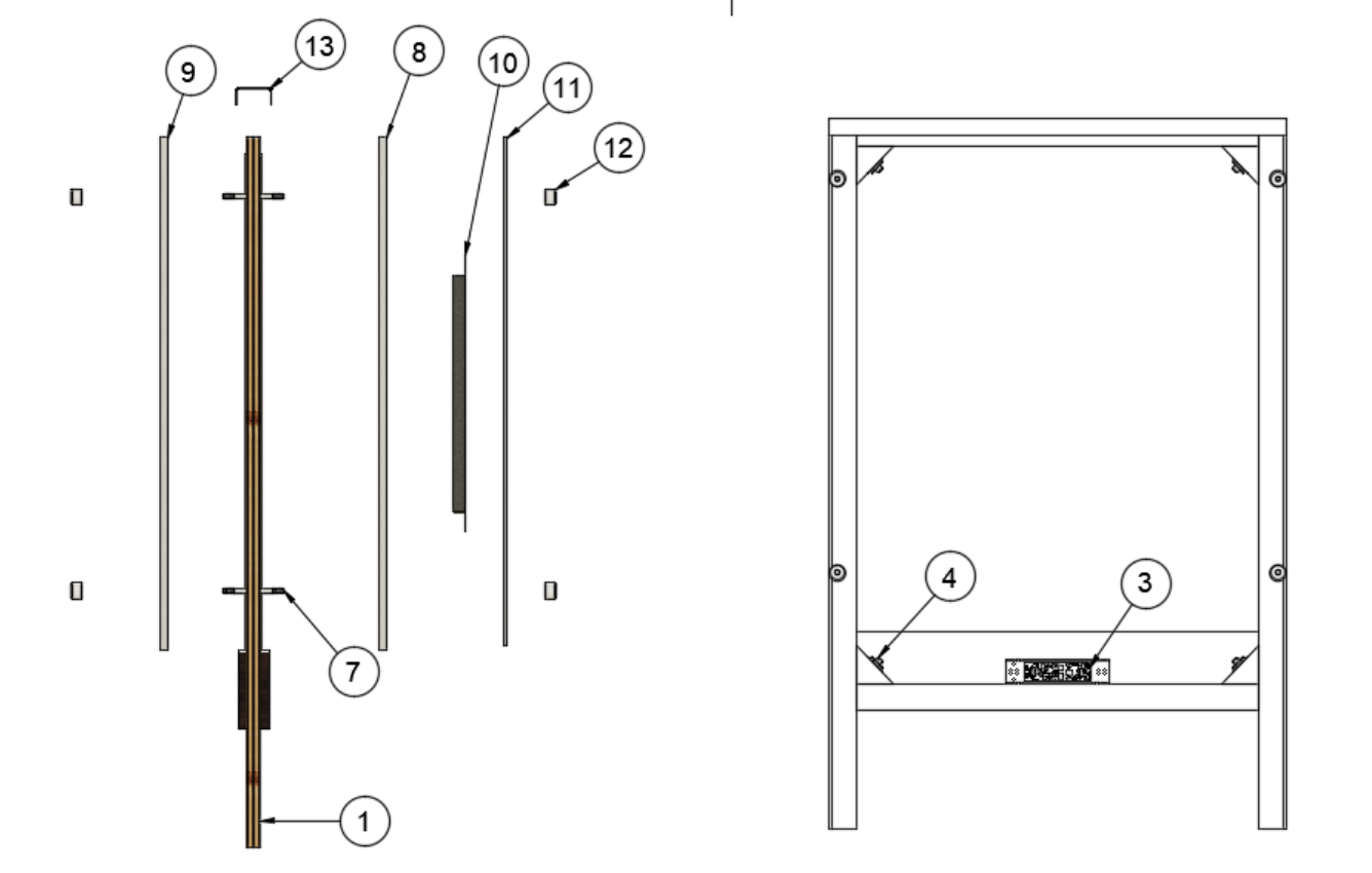
Eksplodert visning
Nedenfor er en eksplodert visning av komponentene som brukes i en vanlig eScore H-skive.
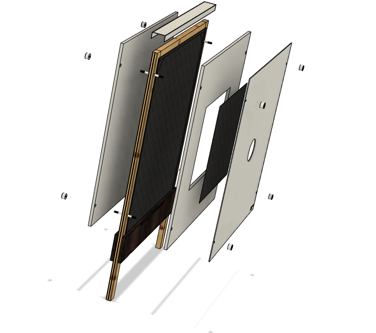
Deleliste
| ID | Beskrivelse |
| 1 | Skiveramme med luker, kabler, akustiske og temperatursensorer og målelektronikk |
| 3 | Skive elektronikk |
| 4 | Akustiske sensorer (x4) |
| 7 | Styrepinner (x4) |
| 8 | Fronttemperaturskjold (Varianter tilgjengelig avhengig av målflaten) |
| 9 | Bakre temperaturskjold |
| 10 | Ekspandert plastplate med gummi (Avvik i henhold til utsparing i temperaturskjoldet foran) |
| 11 | Skiveflate (Kontakt din Kongsberg Target Systems-forhandler for tilgjengelige alternativer) |
| 12 | Styrepinnemuttere (x8) |
| 13 | Skive toppdeksel |
Demontering
Komponentene i skiven kan lett nås uten behov for spesialverktøy. Se videoen nedenfor for å få en rask gjennomgang av hvordan de forskjellige delene settes sammen.
H target video disassembly
Your browser does not support HTML5 video....
Vedlikehold og reparasjoner
For å finne informasjon om vedlikehold og reparasjoner, utvid fanene nedenfor eller finn favorittartikkelen din på docs.kongsbergtargets.com (åpnes i ny fane)
Maintenance intervals H1E
Recommended maintenance intervals of the H1E-target The recommended rule of thumb...
Recommended maintenance intervals of the H1E-target
The recommended rule of thumb rotation intervals are given in the following table:
| Shooting distance | Caliber notes | Rotational frequency |
| 100 m | Using small bore calibers (.22LR, sub-sonic projectiles) together with big bore. In this case only one rubber band must be used | After 500 rounds |
| 100 m | Using only big bore calibers (supersonic projectiles). One or two rubber bands can be used | After 1000 rounds |
| 200 m | Only big bore. Two rubber bands | After 1500 rounds |
| 300 m | Only big bore. Two rubber bands | After 3000 rounds |
Note that the table above assumes normal full jacketed bullets (except 22LR) and relatively good groupings. If groupings are large the intervals can be even longer.
Vedlikeholdsinformasjon, intervaller og prosedyrer
Maintenance of acoustic targets (H)
To achieve optimal reliability and accuracy the following parameters must be fulf...
To achieve optimal reliability and accuracy the following parameters must be fulfilled:
- Even temperature in the target / measurement chamber
- Soundproof measurement chamber
- Little to no irregularities between the main rubber and the rubber band(s)
- Clean sensors
1. Even temperature in the target / measurement chamber
The target is equipped with front and rear temperature shields that minimize temperature variation inside the measurement chamber. If direct sunlight shines directly on the rubber, large temperature spikes and variations in different areas of the measurement chamber.
The temperature shields are designed to minimize such spikes and variations and they also protect the rubber from UV radiation from the sunlight which can cause faster degradation of the rubber material.
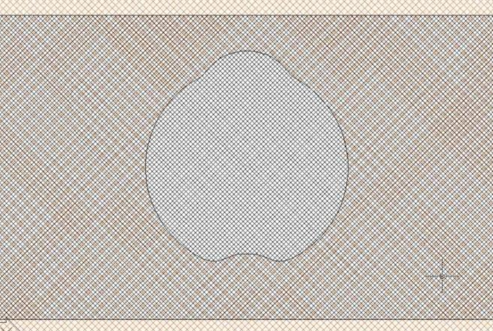
The temperature shields will be shot out in the center after prolonged use. The expanded plastic sheets in the center of the front temperature screen is designed to take most of the normal wear and tear and is a cheap replacement. This should be replaced every time the rubber bands are rotated. The temperature shields themselves are have long lifetime and the rear may be replaced when the shot out area becomes excessively large.
The expanded plastic sheets with rubber are designed to seal the measurement chamber as well and increases accuracy and reduces wear on the rubber bands. When replacing these ensure do remove any debree and/or dirt inside the temperature shield opening before inserting a new plastic sheet.
2. Soundproof measurement chamber
The target is based on acoustic measuring principals. It is therefore important that the measuring chamber is absolutely soundproof, meaning that no acoustic noise can get into the chamber. The target rubber skin and the rubber band on the target serve this function.
Projectiles with supersonic speed generate a very powerful sound energy. It is therefore important that tears from ricochets are repaired. Big holes can be sealed with a rubber patch that is glued to the outside of the target rubber skin with contact adhesive. Smaller tears can be sealed with canvas tape. Contact adhesives will help to increase the grip of such repairs.
An unavoidable fact is wear and tear on the target rubber skin/rubber band from the shooting. After a while of shooting at the target, the holes behind the aiming mark have to be sealed. This is easily done by rotating the rubber band(s).
How often the rubber band must be rotated varies with the following factors:
- Caliber and shape of the bullet
- Spread of the shots. This usually comes down to:
- The shooters skill level
- Shooting distance
Specific recommendations on rotation frequency are found in the "Rotating rubber bands" section.
Shots into the target frame can cause large holes in the measurement chamber if the rubber skin on the target looses contact with the frame. Inspect the frame when doing maintenance to ensure that this is not the case. If this has occured, repair the fault by removing any loose staples, wooden splinters and anything else that can disturb the repairs. Then fasten the rubber skin with staples, glue and canvas tape.
Delete3. Irregularities between the rubber band(s) and the rubber skin
Unevenness between the target rubber skin and the rubber band creates barriers for the sound that will affect the accuracy. It is very important to make sure that the target rubber skin lies nice and tight against the rubber band. If this is not the case it has one of the following causes and solution:
| Cause | Solution |
| The main rubber skin tends to get old, decayed and has bad elasticity . | The target rubber skin must be tightened and maybe changed. See chapter 3.7 for tips on replacing the target rubber skin |
| The edge of the cut-out of the target rubber skin has been hit too many times. This will cause the rubber to hang into the measuring chamber of the target. | The target rubber skin must be replaced. As a temporary solution it can be trimmed with a scissor. Please note that the rubber band must cover the cut-out section at any time |
| Illustration of a nice and tight target rubber skin that lies closely against the rubber band. |

|
| Illustration of a poorly tightened or worn out rubber skin that is bulging away from the rubber band(s) |
|
4. Clean sensors
The H-target models require little - if any - cleaning of the sensors. However we recommend brushing off any debree on the sensors and vacuum dirt and debree inside the target when the rubber skin is replaced. We also recommend annual cleaning of the lower sensors as they are more exposed to dirt and debree. Be careful with the electronics inside the target when doing this.
Sensors are accessed by opening the inspection hatches at the bottom of the target.
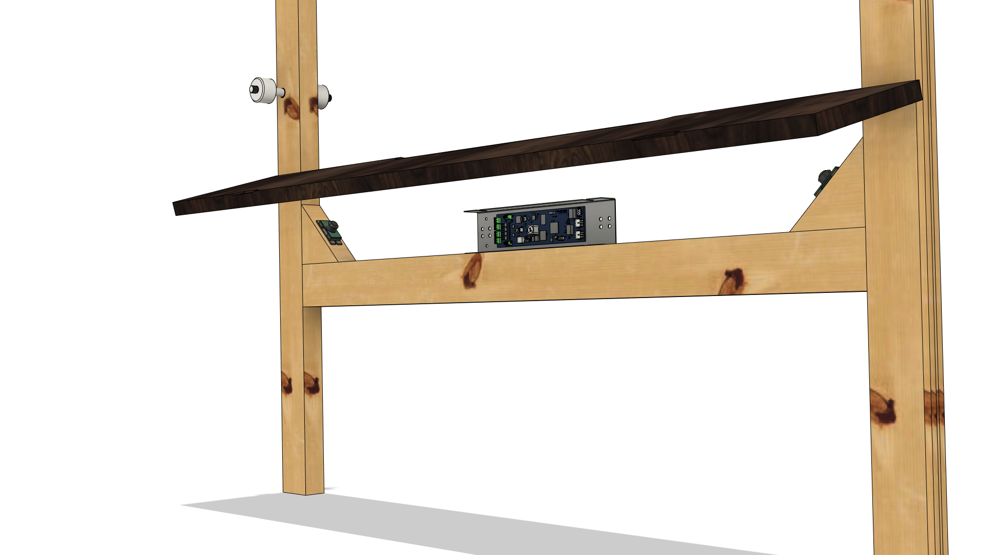 Closeup of sensors and target electronics behind the maintenance hatch
(Rubber skin removed for improved visibility)
Vedlikehold av gummibånd
Maintenance intervals and procedure for rubber band(s)
Recommended maintenance intervals of the H1E-target The recommended rule of thumb...
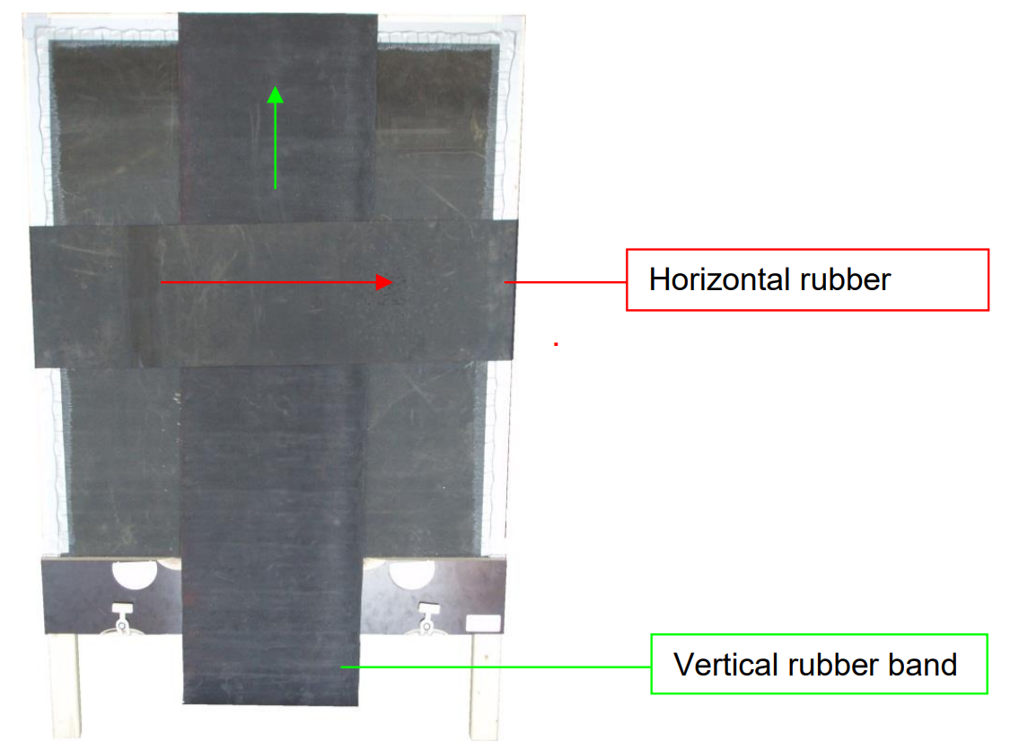
Rotating the rubber band(s)
The target is provided with one and/or two rubber bands (Vertical or horizontal). Every time maintenance is performed the rubber bands should be moved approximately 20 cm. A vertical rubber band is normally moved upwards in front of the target. When rotating a vertical rubber band the top cover must first be removed. It is attached with velcro and is easily lifted off the target.
If your target has both vertical and horizontal rubber bands the vertical rubber band must run INSIDE the horizontal at the front of the target and OUTSIDE the horizontal at the back.
Reparasjoner
Repairing sensors or wiring
Whenever an H-target model is used, one runs the risk of a shooter hitting the up...
Stray shots risk hitting the upper acoustic sensors, upper temperature sensor or their wiring. This section explains how to repair in these cases.
Repairing sensor wiring
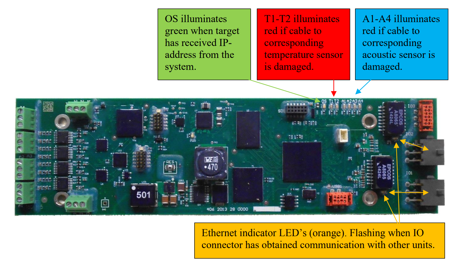
To simplify repairs, all upper sensor wirings are run on the outskirt of the target frame. In the case of a bullet or ricochet cutting a sensor cable, the target electronics will detect that something is wrong with the sensor and also provide warnings to the scoring system. Additionally the circuit board inside the target (the target electronics) will display sensor status by use of LEDs. This circuit board is accessible behind the service panel at the bottom of the target.
Sensor cables may be temporarily spliced with butt splices. However, as a permanent repair cables should be spliced by soldering and sealed with heat shrink tube - if sensor cable isn't replaced. Please also splice the un-isolated leader in the sensor cables.
Replacing sensors
In some cases it might be easier or necessary to replace the entire sensor with wiring harness.
The sensor wires are attached to their respective numbered terminal blocks according to the tables below:
| Connector No. | Attached sensor |
| A1 | Upper right acoustic sensor |
| A2 | Lower right acoustic sensor |
| A3 | Lower left acoustic sensor |
| A4 | Upper left acoustic sensor |
| T1 | Lower temperature sensor |
| T2 | Upper temperature sensor |
The teminal blocks are found at the left side of the board (green components at the image above). Teminal block A1 is the lower left, followed by A2, A3 and the A4 is the upper left block. Each connection point of each termainal block are individually numbered 1, 2 and 3.
For sensors A1-A4 the sensor cable is connected to the terminal blocks as follows:
| Wire | Connection point |
| Red | 1 |
| Black | 2 |
| Cable screen / Ground | 3 |
For sensor T2 the sensor cable is connected to its teminal block as follows:
| Wire | Connection point |
| White | 1 |
| Black | 2 |
| Cable screen / Ground | 3 |
For sensor T1 the sensor cable is connected to its terminal block as follows:
| Wire | Connection point |
| Red | 1 |
| Green | 2 |
| Yellow | 3 |
Replacing the upper acoustic sensors
If the upper sensors are to be replaced a section (corner) of the target rubber skin must be detached the target frame to access the sensor(s). We recommend accessing from the front of the target. The acoustic sensors are taped to an aluminum bracket that is screwed into the target frame.
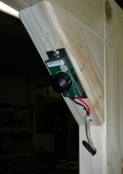 Upper right acoustic sensor mounted on aluminum bracket. The upper right temperature sensor is also visible.
Use the same screws and screw holes when replacing the sensor.
The temperature sensor is supposed to extend only 2-3 cm inside the target frame.
Replacing I/O cables
I/O cables are pre fabricated to specific lengths. The male and the female I/O cables are connected to the target electroniscs IO1 and IO2 box connectors at the right side of the board. Also, cable ground wires are screwed to the metal of which the target electronics is attached.


When ordering I/O cables make sure to choose the connector series fitting rest of the system. See exploaded view parts list at top of this user manual to find part numbers.
I/O cables are attached to target frame with cable clamps and a and some adhesive tape. Install the cables as the original cable harness. Get some cable ties before replacing cables, in addition to canvas tape.
I/O cables are always put in a loop inside target, to obtain maximum strain relief. Prevent loop from touching any nearby sensors by bending the loop in combination with using cable clips. Images below from different target models:
 |
 |
I/O cables should extend approximately 14cm from the underside of the target frame.

Beskyttelse av H1E-målet
Hvordan beskytte H1E-målet mot kuler og rikosjetter
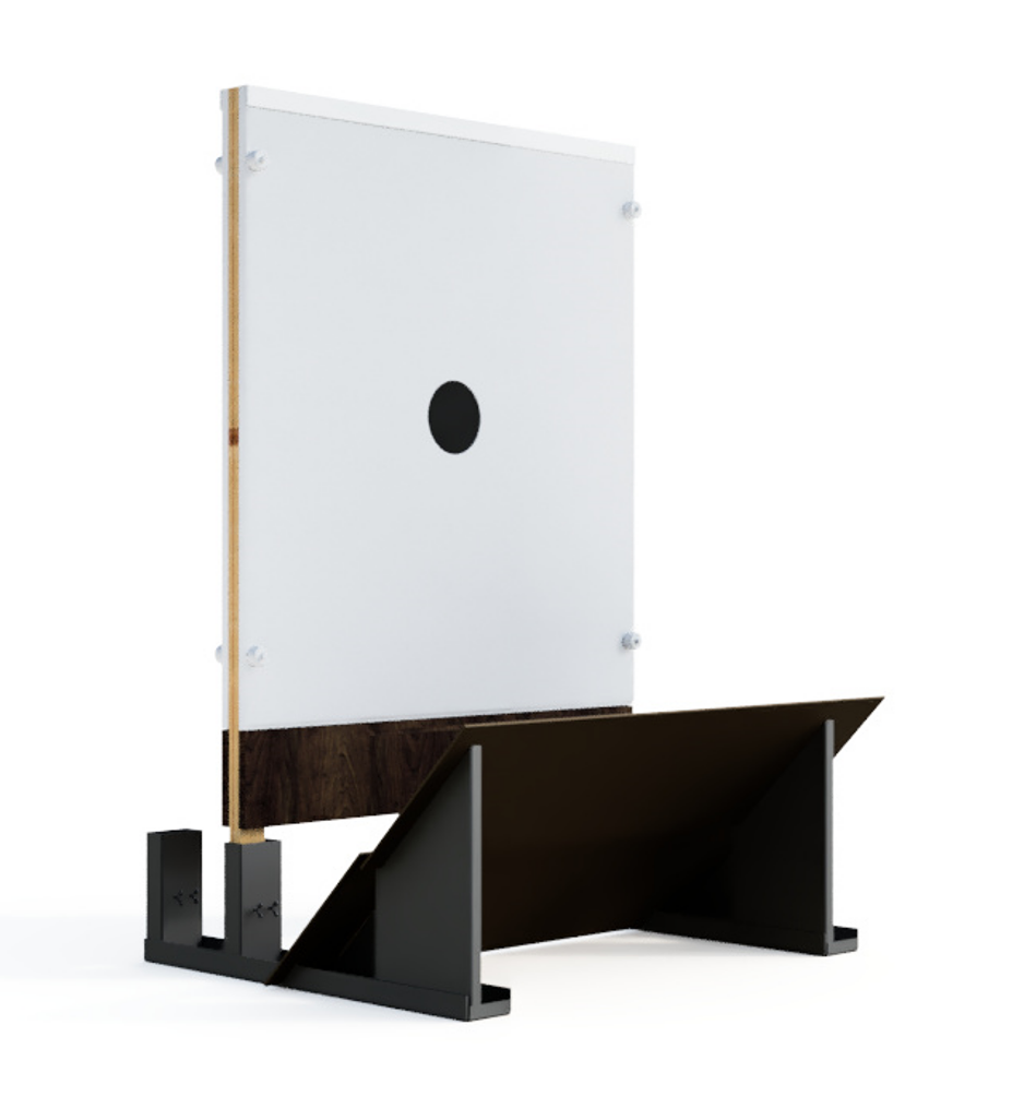
Protecting the eScore acoustic target
The eScore targets have the critical electronics located at the bottom of the tar
The targets have the most critical, or all, electronic components located at the bottom of the target - behind the service panel. To minimize maintenance cost and maintain the target durability it is recommended to protect this section of the target by use of a knee wall or protective plates. Target stands with protective plates are available on request.
Please refer to this YouTube video for recommendations on how to install the targets.
Protection from ricochets and shrapnel
Some shooting ranges have backstop that create shrapnel when bullets hit bullet catchers. This should be avoided since cables may be cut or short circuited by shrapnel or bullet jackets. To minimize the effects careful placement of the wiring between targets, antennas, batteries etc. must be done. If steel bullet catcher is used, make sure to cover it with rubber material or other absorbent material to minimize ricochets and shrapnel exiting the bullet catcher.